How to dial spokes on a front wheel bicycle. How to properly assemble a bicycle wheel. Detailed instructions, balancing tips, many photos
The rear wheel hub of a bicycle is one of the most complex and expensive bicycle mechanisms. It is the rear hub that raises the most questions among novice cyclists. Repairing it or servicing it is generally like a bad dream.
The quality of the bushings determines how much effort you will expend to cover a certain distance, in other words, the “rollability” of the bicycle. The rear hub is subjected to much greater loads than the front, which dictates the need to make it more massive. In addition, if the front hub has only one function (free rotation of the wheel), then the rear hub has additional functions - torque transmission, pedal-free travel, braking functions and even sometimes internal gear shift systems (planetary hubs).
There are quite a lot of companies that produce hubs for bicycles and there is no point in listing them all. It is worth noting Shimano rear hubs; in Russia these are the most common hubs due to their high quality and wide price range.
Like the front bushings, the rear bushings may differ in materials of manufacture, purpose, production technology, weight and strength. But the rear bushings also have their own differences that are unique to them. Which ones will be discussed below.
Materials and technologies for manufacturing rear hubs
In terms of manufacturing methods and materials, the rear hubs do not differ from the front ones. Bushings are produced by casting, turning or stamping. Cast bushings are the cheapest to produce, but they are also the least durable and have the heaviest weight. The most optimal metal for bushings is aluminum alloy. Hubs for the simplest and cheapest bicycles are made from steel. The lightest and most durable bushings are made from titanium alloy, but they are so expensive that they are used only in professional sports bikes.
Rear Hub Types
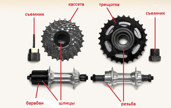
According to application, rear hubs can be for road bikes, high-speed (mountain, touring and highway). Road bicycles are usually equipped with hubs with one driven sprocket and a freewheel mechanism. Also, hubs for road workers are equipped with a drum brake mechanism, i.e. bushing with foot brake. Rear hubs for sports bikes do not have a brake mechanism, but have a freewheel system. In addition, sports rear hubs are divided into cassette and ratchet.
Speed bike rear hub design
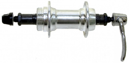
The design of the rear wheel hub of a high-speed bicycle provides for a set of driven sprockets through which torque is transmitted to the wheel. There are two types of rear sprocket sets - cassette and ratchet. If the bushing is designed for a ratchet, then the drum (nut) is located outside the bushing and is integrated into the set of stars. The ratchet itself is attached to the fork using a special thread. If the bushing is for a cassette, then the drum is located on the bushing itself and is attached to it using a special hollow bolt (see diagram). The cassette, in turn, is attached to the drum through a spline connection and secured with a special nut.
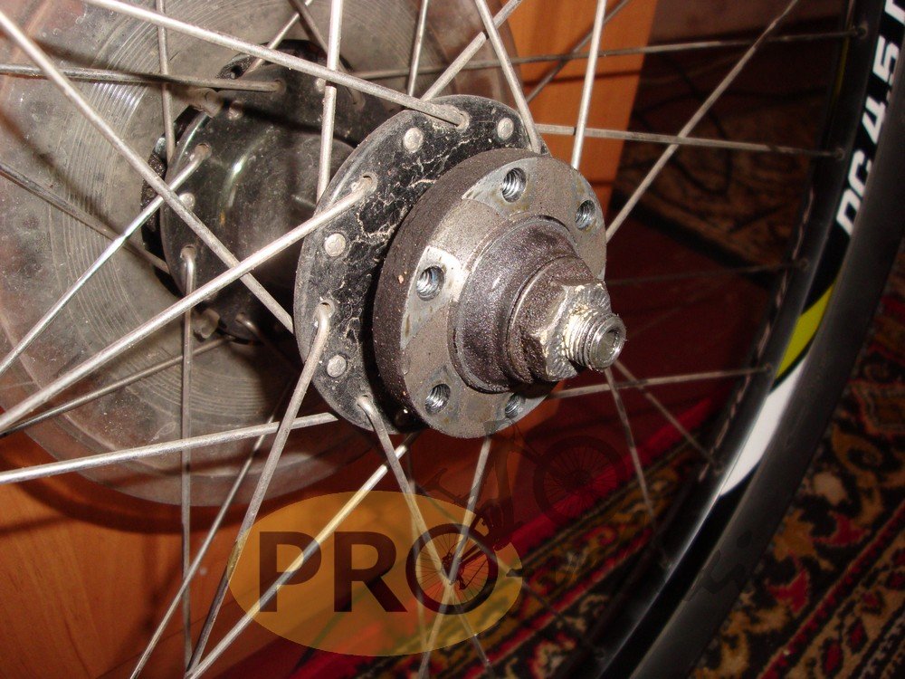
It’s worth adding about the disc brake rotor mounts. Here, like the front hubs, there are two standards - CenterLock and 6 Bolt. The CL standard provides for spline fastening and tightening with a special nut. This standard is patented by Shimano. The six-bolt mount is more popular and is used by all manufacturers of rear hubs and brake systems. Six-bolt rotor with CL mount
Rear hubs with brake
Most single-speed bicycles, whether road or children's, are equipped with a rear hub with an integrated brake mechanism and a freewheel mechanism. Such bushings perform several of the following functions:
- Transmission of torque from the driving sprocket of the connecting rods to the driven sprocket of the rear hub and, accordingly, the wheel itself.
- Free wheel movement relative to the driven star. As soon as the driven star stops, the wheel continues to rotate, regardless of the bicycle pedals.
- The built-in brake mechanism allows you to brake by rotating the pedals in the opposite direction. The essence is the same as in drum car brakes with internal pads.
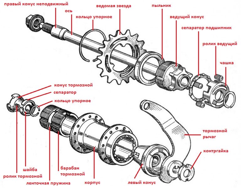
The most common brake bushings are the “Torpedo” type. Such bushings were installed on most Soviet bicycles and are still used in the production of road bicycles today. The oldest Soviet and some imported bicycles from the beginning of the last century were equipped with “Go” type hubs. Also in Soviet times, domestic bushings with the self-explanatory name “Motherland” were developed. The last two types are almost never found at present. Therefore, we will consider in more detail the design of only the Torpedo bushings.

Based on the above diagram, let's look at how processes occur inside the rear hub.
- Working stroke - while turning the pedals, the drive cone, rotating with its protrusions, moves the drive rollers upward, thereby jamming the hub body, thereby rotating the wheel.
- Free play - as soon as the drive cone stops rotating, the housing compresses the drive rollers into the recesses between the lugs, due to this process the connection between the drive cone and the housing is lost. Loss of connection allows the wheel to rotate freely relative to the pedals.
- Braking - when the cyclist begins to press the pedal back, the drive cone begins to rotate in the opposite direction and, thanks to friction, rotates the brake cone with oblique protrusions. The brake rollers fit into the grooves of the brake drum and the brake cone slides into the drum. The drum is moved apart by cones on both sides, pressed against the hub body and brakes the wheel.
The Torpedo type provides the best braking option. The stronger the force on the pedal, the stronger the braking - this ensures smooth braking.
At first glance, it may seem that the rear and front hubs of a bicycle have a complex structure, and it is not possible to repair and service them yourself at home. simple task. But it is not so. Of course there are some design differences, but most are the same. Therefore, in this article we will touch on such topics as: types and design of bicycle wheel hubs, their disassembly/assembly, repair and maintenance, and also consider what, how and with what frequency they should be lubricated. We will try to present the material as briefly as possible in the form of detailed instructions, and at some points we will add a video to illustrate the disassembly of the bushing.
IN this moment On the bicycle spare parts market there are several types of bicycle wheel hubs: with freewheel, without freewheel (used on fix bikes), as well as with a built-in foot brake, with a built-in dynamo, and so-called planetary hubs. In free-wheeling designs, two types of bearings can be used: cone-cup type (mainly from the manufacturer Shimano) and industrial bearings. Since free-floating hubs with an integrated brake mechanism are the most popular, we will look at their design below.
Design of bushings with cone-cup bearings (bulk)
This type of bushing is one of the most common compared to others and is often used on road, mountain, road and other types of iron horses. It can be used on both the most budget bikes and professional bikes. A proponent of this design is Shimano, which produces exclusively bushings with bulk bearings (and planetary bushings). According to them, the cone has an advantage over a bushing with industrial bearings, namely, better rolling. Whether this is true or not is difficult to say, but this is not the purpose of this article. Next, let's look at the design of a typical bushing with cones.
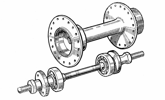
As we can see, a hub with cone-cup bearings consists of: a housing, an axle, cups, balls, boots, cone nuts, washers, boots, locknuts (and a drum, if we are considering the rear hub).
Bicycle hub design with industrial bearings
The design of this type of bushing is very similar to the previous one, with the exception of the use of industrial bearings instead of bulk balls. Because of this, it does not have components such as balls and flare nuts, and the bearing is a one-piece design. The advantages include ease of assembly and disassembly, as well as the lack of need to adjust the tightening of the cones. This type of hubs can also be used on almost all types of bicycles.
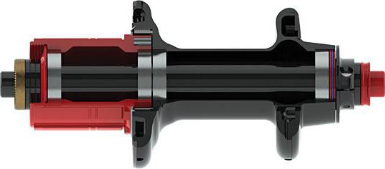
Rear hub design with brake mechanism
This type of hub is installed mainly on single-speed city bicycles. Its main feature is the brake, which is installed inside its body and is activated by moving the pedals backwards. Due to this, it is slightly larger and heavier than its competitors. Below we will show a picture of the design of this bushing.
Planetary and dynamo bushings
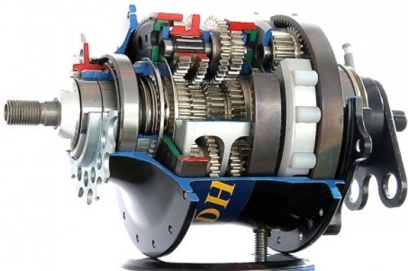
Bicycle planetary hubs are very similar to a small car gearbox and have complex design and tight arrangement of parts. Inside this design there are many gears with which the gears are changed. Difficult to repair and maintain. Can often be used on city folding bicycles.
Bushings with dynamics inside the housing are, roughly speaking, a small generator from which you can power various electrical appliances on a bicycle. For example, these could be lighting lanterns. Basically, the dynamics are located inside the front hub of a city or road bike.
Rear and front hub maintenance
Before we start disassembling, let's decide when to service bicycle hubs. First of all, it is worth noting that maintenance can be periodic and forced.
Periodic Maintenance
This implies preventive measures for cleaning and lubricating all bicycle hub components to avoid their failure, thereby reducing the cost of purchasing new spare parts and repair problems. Many bike mechanics recommend replacing the grease of the hub bearings every 5,000 km, but as practice shows, a lot depends on the road surface on which you ride and the quality of the hub itself (the design of the boots itself). Therefore, the need for maintenance may arise earlier.
Forced maintenance
If, when riding or checking the rotation of a bicycle wheel, you find play, extraneous noise and crackling inside the hub, or there is difficulty in rotating the wheel, then this may indicate several possible reasons:
- Incorrect tightening of the cones (in the case of a cone-cup bearing).
- Lack of lubricant or severe contamination.
- Failure of the cups, balls or bushing cone (in the case of a cone-cup bearing).
- Failure of industrial bearings (in the case of a slip bushing).
In this case, the wheel should be repaired and serviced as soon as possible. We will look at what needs to be done for this below.
How to disassemble, lubricate and assemble the rear and front hub of a bicycle
We will disassemble and replace the lubricant using the example of a bushing with cone-cup bearings.
ATTENTION: When disassembling, clearly remember the sequence in which the bushing components are removed and how they are installed. Also, parts on the left side cannot be installed on the right and vice versa. The latter is because the balls, cups and cones rub against each other and will not fit well if you move them to the other side.
Disassembling the front hub
First, let's disassemble/assemble the front hub of the bike.
Rear hub disassembly
Next, we will look at how to disassemble and lubricate the rear hub of a bicycle wheel. In principle, there is no particular difference from the method of disassembling the front one (so you can read it first, there are points there that we did not repeat in the description for the rear one), except for a few minor differences.
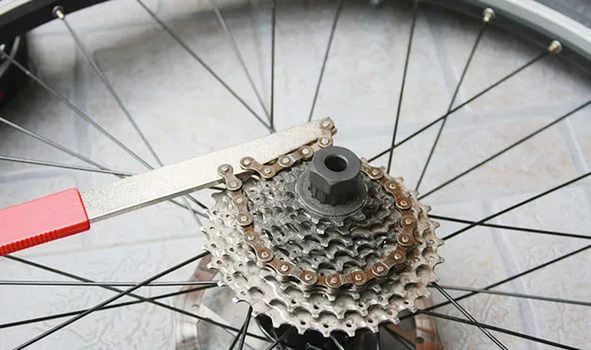
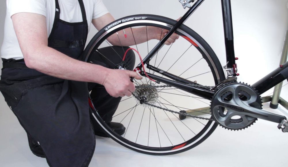
If for some reason you need to remove the cassette, you can do this literally right away using a special tool.
How to lubricate the bearings of the rear and front bushings
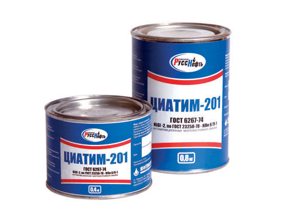
To lubricate the front and rear hub bearings of a bicycle, you can use any thick type of automotive bearing grease. For example, Litol-24 or CIFTIM-201.158 would work well. Of course, no one forbids you to buy specialized bicycle bearing lubricants, for example, from Shimano, which do an excellent job. But to be honest, I didn’t notice much of a difference (except for the price).

But here’s what you shouldn’t use to lubricate the bushing bearings on your bike: WD-40, motor vehicle oils, oils for sewing machines, for lubricating bicycle chains and other liquid lubricants.
Bicycle rear and front hub repair
When parts such as the axle, cone, bearing balls, and cups reach the end of their service life or premature failure, they are replaced with new ones. And if there are no special problems with the first ones on this list, then with cups it’s not so simple. There are a few hiccups. Firstly, it’s unlikely to be possible to buy new ones specifically for a specific bushing (unless you can find the same used one). Therefore, you will either need to dance with a tambourine and order a cup from a turner, or look for a donor, knock them out and insert them into the victim. Which doesn't always work out. There is another option. Knock the cups out of the bicycle wheel hub and install industrial bearings in their place. But here, too, you need to clearly select everything according to size, and not everything can go the way you wanted. So if the cups break, you will most likely need to buy a new bushing.
I would like to note that when replacing balls, you should change them all at once, and not several at a time.
When industrial bearings fail, they can also be replaced without any problems with new ones.
Well, for the rest, clean and lubricate the bushings in a timely manner, check them for play (if necessary, tighten them as described above) and the bicycle bushings will serve you for a very long time.
Video on the topic
Conclusion
After reading this article, you learned how to properly disassemble and repair the rear and front hubs of a bicycle with your own hands using pictures and videos as an example. How can we sum it up? First of all, periodic and timely maintenance should be carried out: clean and lubricate, check for play and serviceability. In addition, we learned what can and cannot be used to lubricate the bushing, and also learned its structure. Thank you for your attention and good luck with your repair!
CategoriesIt's no secret that any vehicle periodically needs repair and maintenance. The bicycle is no exception. And also sometimes this need is due to the desire to modernize your bike. To prepare it for such manipulations, of course, the structure will have to be disassembled, and although a bicycle is not a complex mechanism, not every cyclist has an idea how to disassemble the rear wheel of a bicycle.
Main components of the wheel
Standard bicycle wheel consists of several main parts:
- bushing is the central part that provides torque. Internal organization The rear hub is a little more complicated than the front. Not every bushing can be disassembled at home; some variations are best left alone without special equipment and knowledge. Brakes can also be attached to this part;
- spokes connecting the hub to the rim;
- the rim on which the tire is mounted;
- tire.
So, if you need to repair the rear wheel of your bicycle, or it’s simply time to service the spare parts, you need to clarify the procedure that should be carried out when removing the wheel.
Dismantling sequence
First, we remove from the bicycle all unnecessary objects that may be on it. And it is also better to unscrew all kinds of mirrors, flashlights and other small things that may be damaged during work.
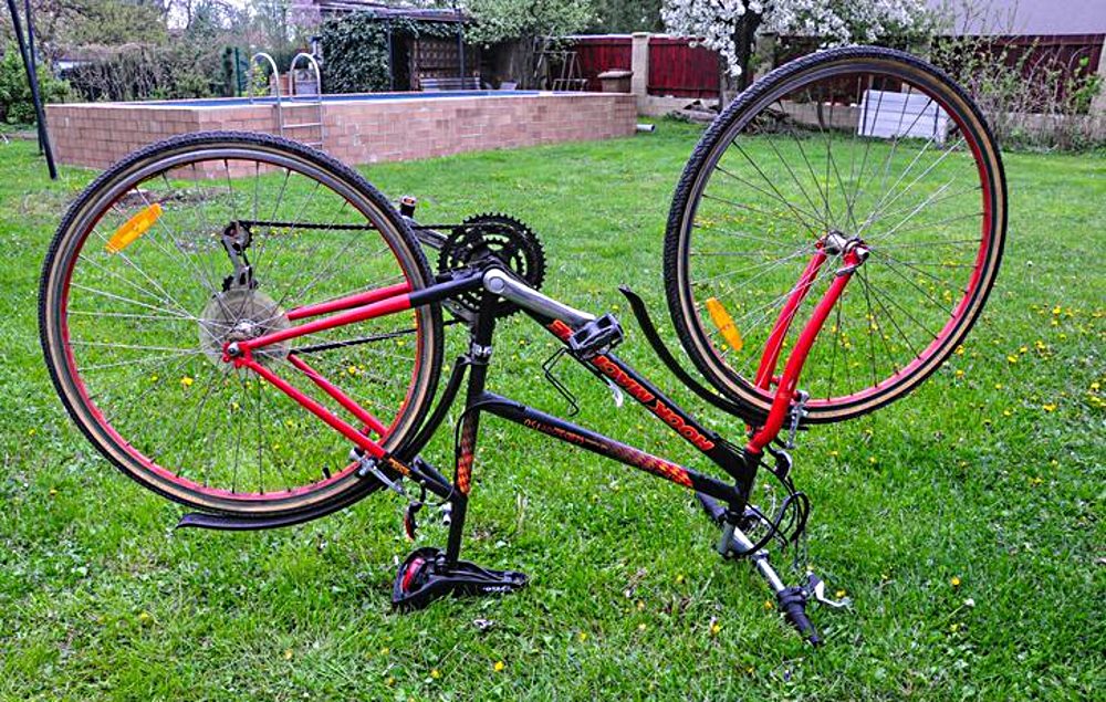
- We turn the bike upside down and place it on the handlebars and seat. You can do without a special rack for repairing a bicycle, the main thing is to give it a stable position.
- We find out the type of brakes installed for the next course of action. As usual, these are disc or rim brakes:
- disc brake. It will make it easier to remove the wheel;
- The V-brake type rim brake must first be released and removed, otherwise further removal of the wheel will no longer be possible. . (It is not difficult to unfasten the brakes; to do this, you need to move the cable towards the fastening screw, move the levers, bringing the end of the cable out of the clamp, lower it down and move the brake levers to the sides).
- Next we proceed depending on the type of mounting of the rear wheel on the bicycle axle. We unscrew the nuts using a wrench (one or two) or, if the fastening is a disc eccentric, we unscrew the brake lever and twist the wheel.
- The chain passing through the gear shift system is carefully removed from the sprockets.
The wheel has been removed. Now you can carry out all the necessary further manipulations: replacement, adjustment, lubrication of parts.
Replacing the camera
First of all, you need to deflate the tire - unscrew the cap and press the nipple to release the air. If the chamber is damaged and there is no air in it, simply remove the cap. To remove the tire, you will need mounting blades, which will conveniently pry the tube until it becomes possible to easily pull it off the rim.
You can install the camera in place without the help of tools. First, the nipple is inserted into the hole in the rim, after which the tire is evenly placed on the rim. Finally, the camera needs to be pumped up to the desired state.
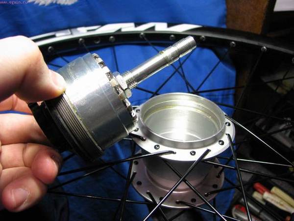
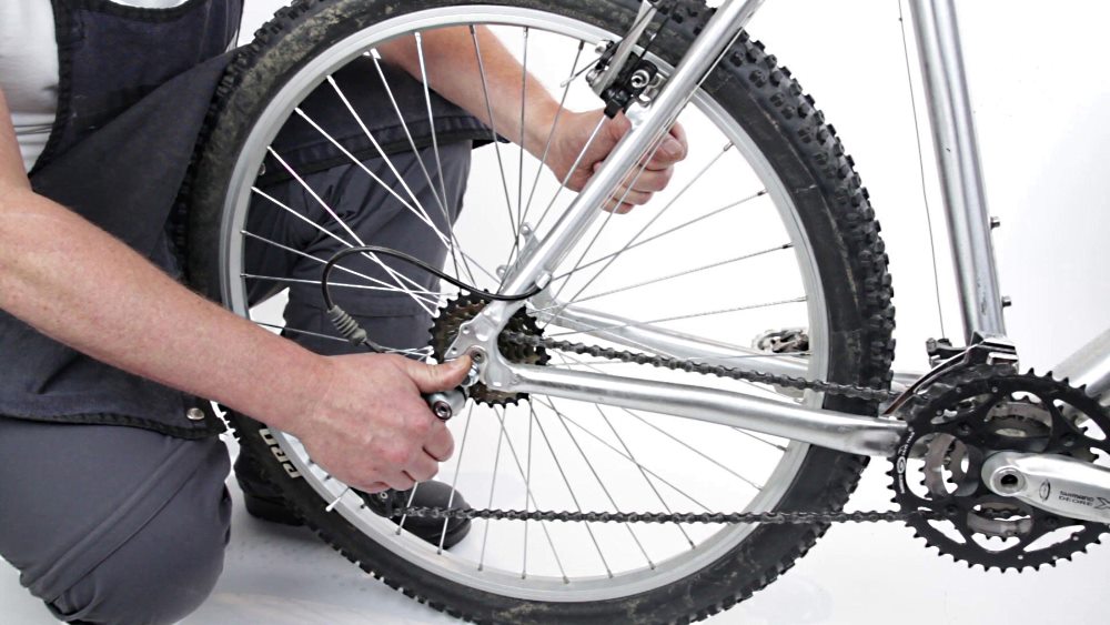
Removing the Bushing
We remove the cassette with sprockets using a special puller, a key and a whip. First, we insert the puller into the nut, then insert the key into it, put a whip on the large sprocket, hold the sprockets with it, and unscrew the nut. Now that the nut is unscrewed, you can easily remove the sprocket cassette.
Before disassembling the bushing, you should loosen the tension of the spokes so that it can be easily pulled out of the gears. When disassembling this part, it is better to arrange all its components in order, so that later you can accurately assemble everything in place. If necessary, you can replace bearings, which, unlike metal components, are the first to fail. Timely maintenance of the bushing will ensure its long service life, so do not neglect cleaning and lubricating the mechanism parts.
IN reverse order action, the spokes are tightened exactly as much as they were loosened; it is important not to overtighten them, but the parts must be firmly fixed. The cassette is put on the sleeve and tightened with a whip.
After all the procedures performed, due to which the wheel and its parts were dismantled, you need to know how to assemble rear wheel bike back.
Rear wheel installation
To carry out the installation correctly, everything should be put back in place exactly in the reverse order.
- Place the chain on the smallest sprocket and insert the wheel onto the frame mount. In this case, it is important to make sure that the axle is completely inserted into the grooves of the frame.
- We fasten the nuts or eccentrics; they should be tightened well so that the wheel sits firmly on the frame.
- If you have rim brakes, they should be fastened. Return to the previous position strictly in reverse order, otherwise the next trip may not end very well.
After the installation process, it is advisable to check the correctness of the actions taken through a short test drive to see how your bike will behave on the road after the updates.
Maintenance and diagnostics of the rear wheel is a mandatory procedure to maintain the health of the mechanisms.
Everything is possible. Assembling a wheel is labor-intensive and requires certain skills. Typically, an experienced mechanic will spend less than an hour assembling a wheel, but once upon a time he spent much more time on it. Assembling wheels is not impossible, it just takes a little patience and consistency.
There are many types of wheel spokes, the main ones being “radial” and “cross”. We will look at the knitting pattern - 3 crosses. This means that each spoke will be crossed three times. This is the most common knitting needle, time-tested.
Let's break down the complete wheel assembly into several stages:
- Preparation;
- Installing spokes or stuffing a wheel;
- Adjustment and tension of the spokes;
First stage consists in determining the required length of the knitting needles. While the front wheel has the same length of spokes on both sides, the rear wheel is more complex. Due to the presence of speeds and the requirement that the wheel be centered, the spokes will have different angles, and therefore different lengths.
To determine the length of the knitting needles, you can use calculators that are not difficult to find on the Internet. Suitable as one of the options.
The calculator will prompt you to make some measurements of the hub and rim and based on this, the spokes will be automatically calculated. The calculator has illustrations showing what needs to be measured.
On second at this stage we will need:
- Rim;
- ;
- ;
- Screwdriver and spoke wrench;
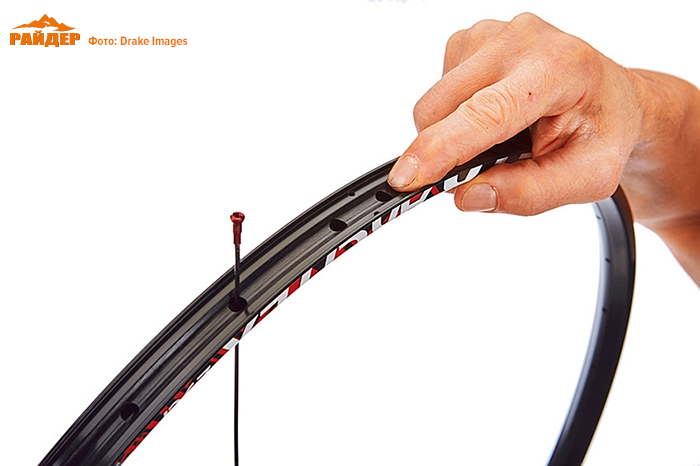
The rim has spoke holes that are slightly angled/offset to the left and right. This is worth paying attention to. The spokes from the right flange of the hub should be inserted into the holes shifted to the right side, from the left flange - to the left side.
The spokes are divided into 4 groups: half of the spokes of the right flange and the second half of the left flange. Each flange, in turn, has half of the “leading” spokes and half of the “tail” spokes.
Leading spokes
– spokes directed along the direction of rotation of the wheel. Indicated in shades of blue.
Tail spokes
– spokes directed against the direction of rotation of the wheel. Indicated in shades of red.
We will attach the spokes to the rim in groups.
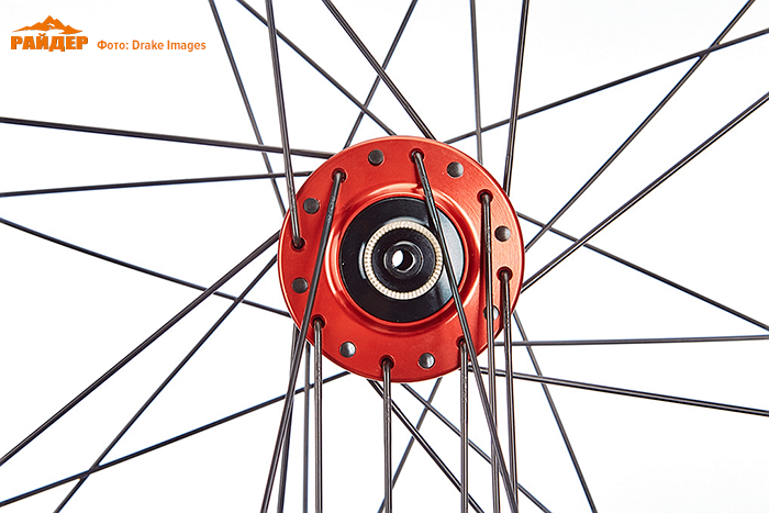
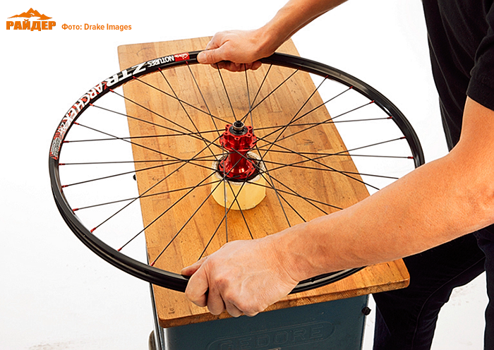
On the aesthetic side, professionals align the sleeve markings so that they are visible through the hole for the camera nipple. If you hold the wheel with the right side facing you (if it is a rear wheel, then with the sprocket drum towards you) and the hole for the chamber nipple (spool valve) at 12 o'clock, then just turn the hub so that the marking faces 9 o'clock and start the spokes from the top hole of the flange bushings.
The first spoke we install will be called key
.
This knitting needle must be in its place. The key spoke is a tail spoke and will run inside the flange (the head is located outside). The spoke is inserted with outside the right flange and is directed into the rim hole, following the spool hole (clockwise), which is shifted to the right side. If the first hole is shifted to the left, then insert it into the next one, it should be exactly shifted to the right.
Tighten the nipple a few turns so that the spoke does not fall out.
Then we pass the next knitting needle through one hole of the same flange and direct it into the hole next 3 after the key one. This should be continued until all the spokes of the first group are in place.
For a rim with 32 spokes, each group consists of 8 spokes. 
Now let's turn the wheel over so that the left flange of the hub is directed towards us. The holes on the right and left flanges do not match. This can be checked with a knitting needle.
Let's move on to installing the second group of spokes. These spokes will also be tail spokes and will run inside the flange (inserted from the outside). 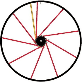
Turn the rim so that the spool is on top. Now the key spoke is to the left of the spool.
- If the key spoke is in the first hole after the spool, then the first spoke of the left flange should be located to the left of the key spoke and is directed into the rim hole to the left of the key spoke.
- If the key spoke is in the second hole after the spool, then the first spoke of the left flange should be located to the right of the key spoke and is directed into the rim hole to the right of the key spoke (between the spool and the key).
If done correctly, the key spoke will not intersect with the newly installed spoke. We install the remaining knitting needles of the second group according to the same rules.
When finished, we have all the tail spokes installed. The rim is filled according to the 2 spokes 2 holes rule. 
Now let's move on to installing the leading spokes. Turn the wheels over so the right flange faces you.
Spoke installation will now occur with inside flange - the spokes are on the outside, the head is on the inside.
Insert the knitting needle into any hole. Turn the hub clockwise so that the leading spoke intersects the 3 tail spokes. Moreover, it crosses the first two from the outside, and the third from the inside. You will have to bend the lead spoke a little so that it goes under the tail spoke. We have two free holes on the rim; we also insert this spoke into the hole in the rim corresponding to the side of the flange (right).
We install the remaining leading spokes. 
If something doesn’t work out, then it’s worth checking the correct location of the knitting needles. After all the spokes have been installed, you should once again check the location of the spokes so that on the rim the spokes go alternately to the right and then to the left flange.
Next comes the initial adjustment, based on uniform tightening of the nipples. We tighten all the nipples by the same number of turns (you can start with 2-3 turns), so that the spokes have approximately the same tension. But they shouldn't be too tight.
The leading spokes are typically curved near the flange. Before you begin to tighten the spokes, you should bend them by hand, pressing each spoke a few centimeters from the flange so that they are better pressed against the flange.
Friends! This is probably not quite the Twentysix format, but I decided to post this small guide from the magazine here so that everyone has the opportunity to evaluate and discuss the format of the regular “Workshop” column. Also because, in the near future, we will try to carry out “import substitution” in relation to this category using one of the domestic bicycle workshops.
So, the motto of the article: “Independent spokes will certainly make you related to the bike. From you - skill and patience. From "Ryder" - step-by-step instructions."
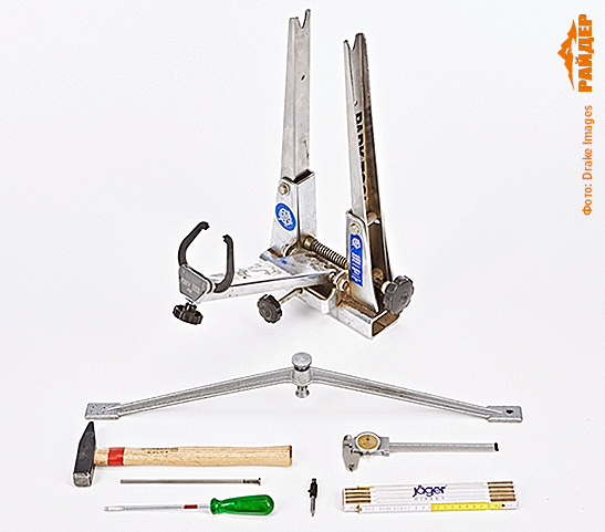
1. To assemble the wheel (with camera) we will need: a wheel centering machine, an umbrella gauge, a caliper, a hammer, a blunt punch, a screwdriver, a folding meter, and a suitable spoke wrench of approximately 3.2 mm for standard square nipples.
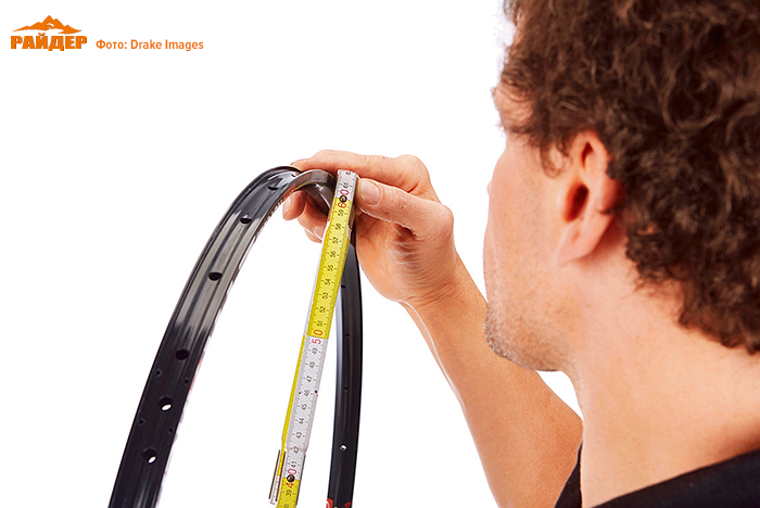
2. First, we measure the effective diameter of the ERD rim: carefully measure inner diameter rim and add the thickness of the rim wall. We will need this figure to calculate the length of the knitting needles.
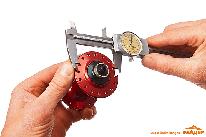
3. Now let's measure the diameter (circumference) of the location (centers) of the spoke holes of the hub. Please note that the diameter of this circle can be different for each flange. And in most cases the front and rear hubs differ in this indicator.
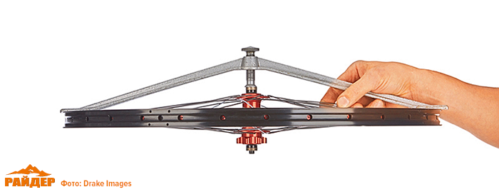
4. We prepare a “passport” for each bushing. We enter the diameters of the location of the spoke holes in it. Then we measure the length of the bushing axis (in this case – 142 mm). Divide this number in half and mark the middle of the sleeve. Now, having positioned the bushing on the sheet according to the drawing, measure the distance from its middle to each of the flanges (FD) using a caliper. In our case it is 33 and 20 mm. Note that due to the mounting of the brake rotor, the front hubs are also asymmetrical.
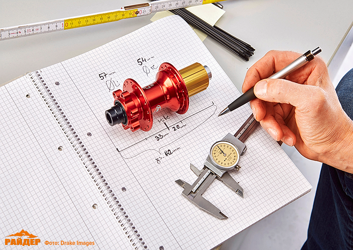
5.
To calculate the length of the spokes, we recommend using one of the online calculators. For example, the spoke length calculator on the DT Swiss website.
Translation of terms for the calculator: Front wheel – front wheel; Rear wheel – rear wheel; Rim Diameter / ERD – rim type and/or ERD (see above); Hub – bushing; Pitch circle diameter – PCD (see above); Flange distance – FD (see above); Ø of spoke hole – diameter of the spoke hole; No. of spokes – number of spokes; No. of intersections – number of intersections (type of spokes, in this case – three); Nipple – nipple type; Spoke length (precise) – exact length of the spoke; rounded – rounded length.

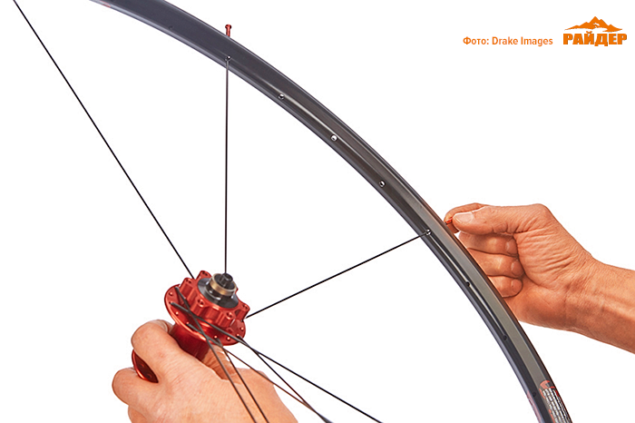
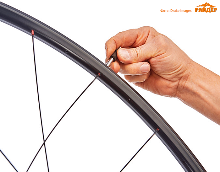
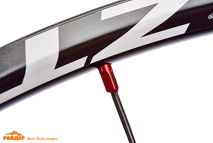
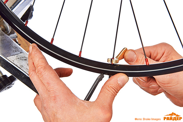
6. We pass the first spoke through any spoke hole in the hub flange from the inside on the rotor side and secure the spoke with a nipple in the second spoke hole of the rim from the hole for the camera nipple (bottom photo).
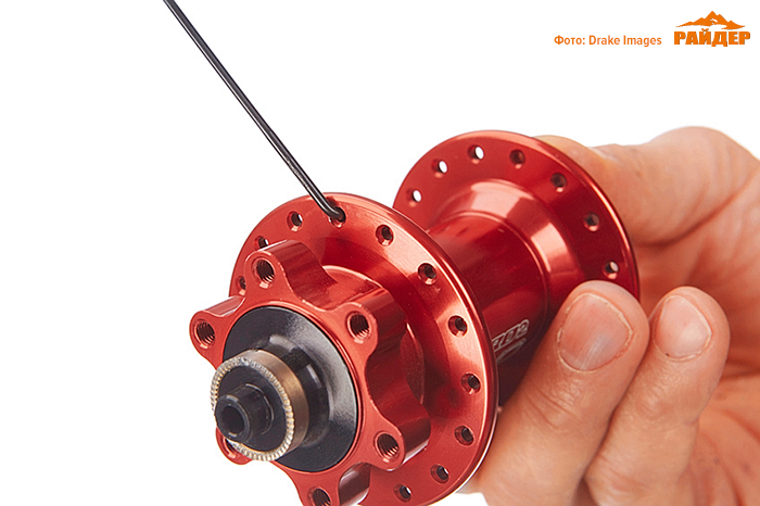
8. Having threaded the spoke through the hole in the hub flange (step 6), insert its end into the hole in the rim, leaving three free holes between adjacent spokes. Secure with nipples. That is, every fourth hole should have a spoke.
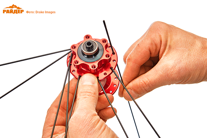
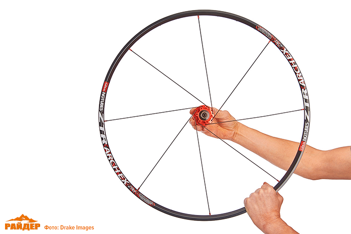
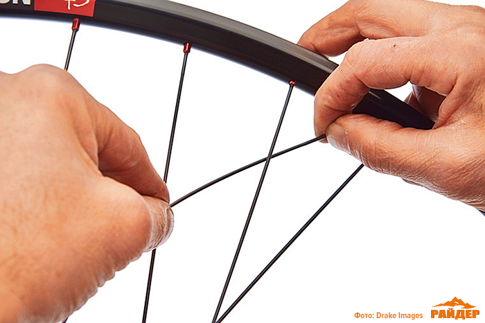
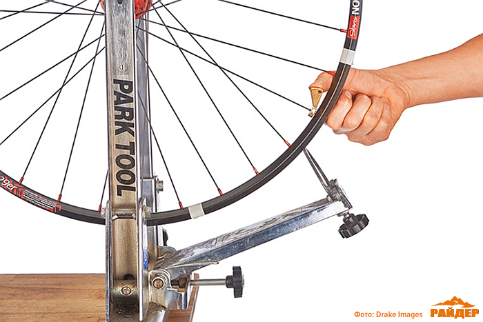
9.
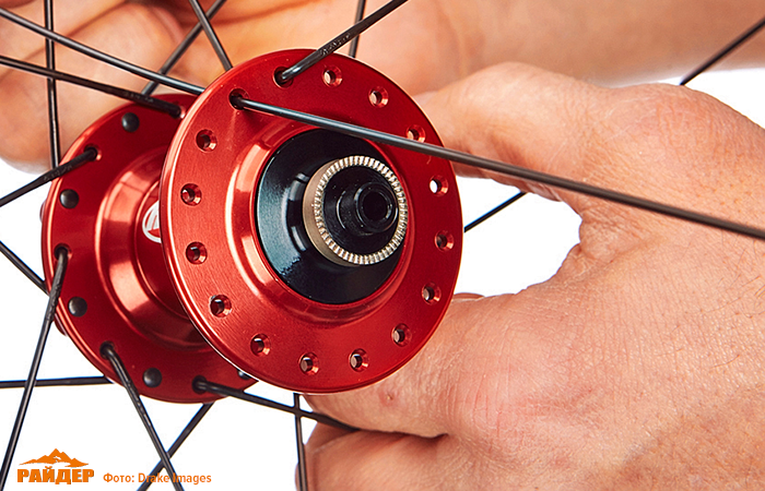
Now we bring the spokes to their working position: holding the rim with one hand, we rotate the hub opposite to the direction of movement (see photo). The spokes should enter the rim at an obtuse angle.
10. We complete the spokes on the rotor side. To do this, we thread the next eight spokes through the remaining holes of the same hub flange from the opposite (outer) side.
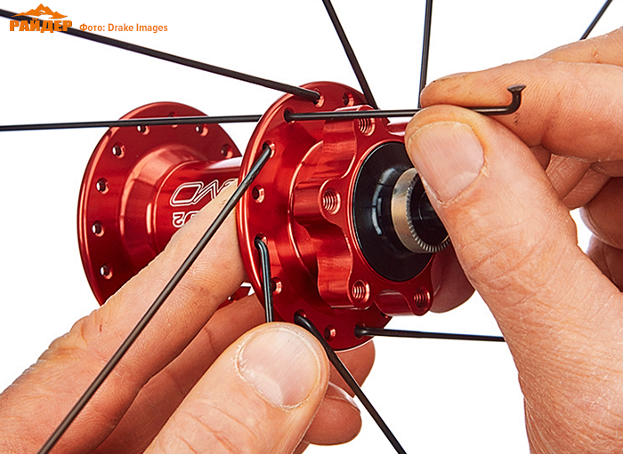
11. Turning the loose threaded knitting needle in the direction of rotation of the hub (see step 9), we draw it behind the two closest fixed knitting needles and in front of the third. Then, as shown in the photo, we thread this spoke into the middle of the three free holes on the rim and secure it with a nipple. We do the same with all the other threaded knitting needles.
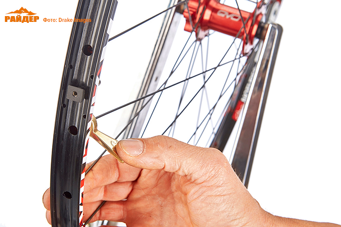
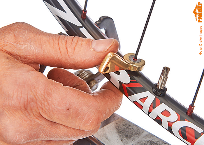
12.
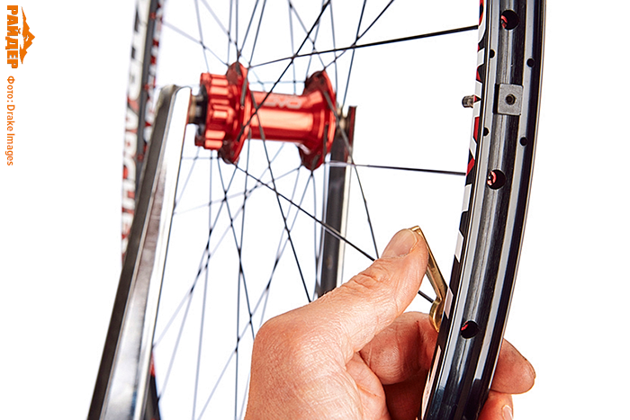
There are splines on the thickened (end) part of the spoke nipples. Inserting a screwdriver or a socket wrench for spokes into the slot (see photo), screw the nipple onto the spoke two or three turns without using force.
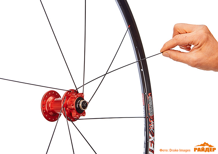
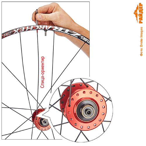
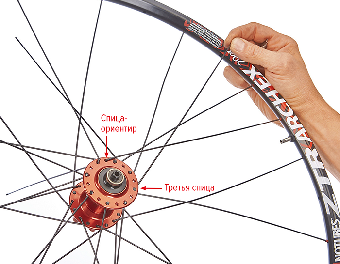
13. Now we pass the first “reference spoke” (not to be confused with the “leading ones”) through the hole in the second flange from the inside. Before doing this, turn the wheel so that the tire valve is at the highest point. Focusing on the rim hole closest to the nipple in the direction of travel of the bicycle (on the left), we find the corresponding hole on the hub flange, also located in the direction of travel (see photo). We fix the knitting needle in this position. This way, there will be no intersection of spokes opposite the tire valve that would interfere with connecting the pump.
14. We insert the next knitting needle into the nearest hole in the flange to the left of the knitting needle - landmark. We thread this knitting needle into the hole from the outside, so that its head looks outward from the hub.
15. We thread the remaining seven knitting needles into every second hole in the flange (we do not insert them into the rim yet). At the same time, we make sure that the knitting needle does not fall into the triangle between the knitting needles of the other side, but remains free. Let's throw it over third knitting needle from the right from the reference spoke through it from the outside and insert it into the nearest free hole from the tire valve on the left (the “back, back, front, secure” principle). We insert the remaining spokes sequentially into every fourth hole of the rim so that they do not intersect with other spokes, and secure them with nipples.
16. We thread the remaining eight knitting needles in the same sequence from the inside of the flange into the free holes. Then they will need to be inserted into the free holes of the rim and secured.
17. Since all the other spokes are already secured, there is quite a bit of room for maneuver. Therefore, we take each of the last spokes with both hands and insert them into the corresponding hole in the rim, observing the pattern of three intersections “back, back, front” and the same angles of intersection of the spokes.
18. Now that we have a complete umbrella, we screw the nipples deeper onto each spoke until all the threads are out of sight - but no further!
19. Now we fix the wheel in the centering (editing) machine. To ensure that the wheel alignment line does not deviate to one side, we check that it is firmly fixed in the machine’s “fork” mounts. Then, starting from the tire valve, tighten all the short spokes of the wheel one full turn. On the front wheel it will be the left side in the direction the bike is moving, and on the rear wheel it will be the right side (transmission side). Then we move on to the knitting needles of the opposite side.
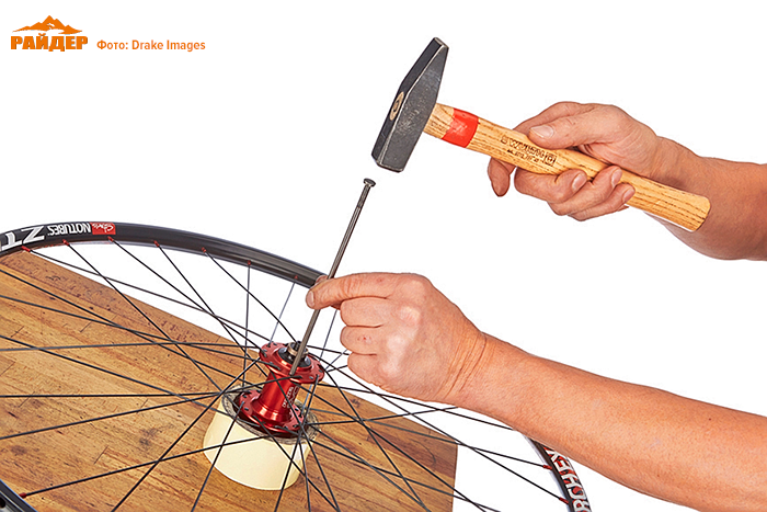
20. It is necessary to prevent friction of the spoke heads against the holes when the spokes vibrate. To do this, with careful blows using a hammer and a blunt punch, we align the head of each knitting needle with the surface of the flange.
21.
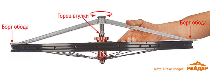
We tighten the spokes about a couple more turns in the sequence indicated above (first on the “short” side, then on the side of the long spokes). We remove the wheel from the machine and install the umbrella gauge on the end of the wheel hub on the side of the short spokes and on the rim on both sides. Using the adjusting wheel, we adjust the length of the umbrella axis in such a way as to eliminate the gaps at these three points (rim sides on the right and left, end of the bushing). Then we apply the umbrella gauge on the opposite side of the wheel (with long spokes).
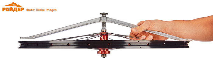
22. If the rim is not equidistant from the hub, tighten all the spoke nipples on the corresponding side of the flange by half a turn. The adjustment should always be towards the long spokes. We check the result of the broaching by again installing the umbrella gauge on the wheel and aligning it.
23. We bring together both probes of the wheel dressing machine and bring them to the rim until one of the probes begins to cling to the rim. To straighten the ellipse, the nipples are always tightened only a quarter of a turn. Always pulls up same number spokes left and right.
24. We mark the radial runout area with white tape. Tighten the spokes (clockwise relative to the outside of the rim) a quarter turn. And, if the runout area covers only five spokes, we slightly tighten the sixth one too, so as not to make a figure eight.
25. The figure eight is indicated by the lateral runout of the rim on the machine probe. To straighten it, slightly loosen the nipples on the beating side and tighten the nipples on the opposite side until the rim stops squeaking against the feeler gauge.
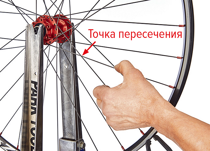
26.
Excessive tension can damage both the hub and the rim. To check the tension, squeeze two crossed knitting needles with medium force. The intersection point should not move more than one centimeter.
27. After all the broaches, you need to check the concentricity of the wheel again. If necessary, we correct it. We just make sure not to “tighten” the knitting needles.
28. To prevent the appearance of figure eights and ellipses, the wheel should be “crimped” after spoketing. We place the wheel on a strong stand and carefully lean on it with our weight, after which we again check it for concentricity and runout.
Author of the text: Christian Cymek