Water supply system of a multi-apartment high-rise building. Topic: Water supply and sanitation of a residential building
Drainage of a residential building- this is a sewage disposal domestic water from residential and non-residential premises apartment building or a residential building, as well as from premises that are part of the common property of an apartment building, through centralized sewerage networks and in-house engineering systems.
Relations in the field of water disposal are regulated by the Federal Law of December 7, 2011 N 416-FZ “On Water Supply and Water Disposal”. Reset Wastewater into a water body is regulated by water legislation.
General rules for drainage are established by Article 7 of Chapter 3 Federal Law dated December 7, 2011 N 416-FZ, and the provision utilities for sanitation in apartment buildings and private residential buildings is carried out in accordance with the Rules for the provision of utility services to owners and users of premises in apartment buildings and residential buildings, approved by Decree of the Government of the Russian Federation of May 6, 2011 N 354 (hereinafter referred to as the Rules).
Conditions for the provision of utility services for wastewater disposal to owners and users of premises in apartment building are determined depending on the chosen method of managing an apartment building.
Estimated volume of municipal resource for wastewater disposal for billing period determined based on the total volume of cold and hot water consumption.
Requirements for the quality of public services for wastewater disposal are defined in Appendix 1 to the Rules:
- Uninterrupted 24/7 water supply throughout the year
- Permissible duration of interruptions in the provision of public services and permissible deviations in the quality of public services:
permissible duration of water supply interruption:
no more than 8 hours (in total) for 1 month, 4 hours at a time (including in case of an accident) - Conditions and procedure for changing the amount of payment for utility services when providing utility services of inadequate quality and (or) with interruptions exceeding the established duration:
for each hour of exceeding the permissible duration of a water supply interruption, calculated in total for the billing period in which the specified excess occurred, the amount of payment for utility services for such billing period is reduced by 0.15 percent of the fee determined for such billing period in accordance with Appendix No. 2 to the Rules, taking into account the provisions of Section IX of the Rules
- Permissible duration of interruptions in the provision of public services and permissible deviations in the quality of public services:
News on the topic
Popular answers to questions about housing and communal services
Do you want your apartment not to blow from the cracks, not to drip from the ceiling, and not be afraid to go into the elevator? So that your home becomes an elegant beauty, in which living is both prestigious and comfortable?It's hard to believe, but it's quite real. Moreover, you will spend much less money on the “magical transformation” of your apartment building than, for example, on buying wallpaper for a bedroom. Just imagine: the cost of several rolls of wallpaper and a transformed house that hasn’t seen renovations for years! 95 percent of the money needed for repairs will be allocated by the state. You just need to take the initiative and collect the missing 5 percent (we emphasize once again: in terms of each owner of an apartment in your building, the amount is a very small amount, for which, moreover, as a rule, installments are established). Do you already want to take part in the housing and communal services reform program in Russia? Of course, you have a lot of specific questions. We tried to answer them in a concise but succinct form...
In accordance with the Rules for the provision of utility services to owners and users of premises in apartment buildings and residential buildings (hereinafter referred to as the Rules), approved by Decree of the Government of the Russian Federation of May 6, 2011 N 354, owners and tenants of residential premises in an apartment building bear obligations for payment of consumed utilities in an amount that ensures full reimbursement of the corresponding costs of the management organization. Those. owners and tenants of residential premises pay not only for individual consumption, but also for the consumption of communal resources for general house needs...
EDUCATIONAL INSTITUTION
"BELARUSIAN STATE UNIVERSITY OF TRANSPORT"
Faculty: "Industrial and civil engineering"
Department: “Ecology and rational use water resources»
Course work
in the discipline: "Engineering networks and equipment"
on the topic: “Water supply and sanitation of a residential building”
Performed:
student of group Mon-31
Checked:
Art. teacher
Belousova G.N.
Introduction
1.1 Selecting a cold water supply system and scheme for the facility being designed
1.4 Selection of water meter
2.1 Selecting a facility’s drainage system
2.2 Hydraulic calculation of outlets and pipelines of the intra-block drainage network
Conclusion
Bibliography
Introduction
A water supply and sanitation system is necessary for comfortable housing; If you make the right choice of water supply and sanitation scheme, you will ensure a reliable, constant supply of water to consumers and disposal of wastewater.
Target course work: determination of design water flow, hydraulic calculation of internal water supply network, selection of a water meter, determination of the estimated flow rate of waste liquid, assignment of sewer pipe diameters, determination of the throughput of sewer outlets and the yard sewer network.
The water supply system includes cold and hot water pipes. The main requirement for their design is to ensure water flow corresponding to the estimated number of water consumers or installed water distribution devices.
The internal drainage system is designed to remove wastewater from buildings. Wastewater discharge is provided through gravity pipelines.
According to the assignment of the course work, it is necessary to design water supply and sanitation systems for a 5-story, 30-apartment residential building in Vitebsk:
floor height - 3.2 m,
basement height - 2.6 m.
first floor floor elevation -46.0 m,
ground surface elevation - 45.1 m.
City water supply with a diameter of 150 mm,
City drainage network with a diameter of 250 mm.
The depth of penetration into soil at zero temperature is 1.5 m.
The guaranteed pressure in the city water supply is 23 m.
1.Design of internal water supply
.1 Selecting a cold water supply system and scheme for the facility being designed
The internal water supply system consists of an inlet, a water metering unit, a main line of risers and connections to water distribution devices.
We design the internal water supply network using a dead-end design with bottom wiring. With lower wiring, the main line connecting the water supply inlet with all water risers is laid within the basement at a distance of 0.52 m from the floor of the first floor.
From the water risers, connections are designed to all water distribution devices. Water risers on floor plans and basements are depicted as dots and designated: St V1-1, St V1-2.
Guided by the location of the water risers and the location of the input, we trace the water distribution main. From the distribution main we make connections d=25mm to watering taps placed in niches of external walls measuring 250 ×300 mm at a height of 350 mm from the blind area at the rate of one watering tap per 60-70 m of the perimeter of the building.
In accordance with the placement of the water risers, distribution main, water metering unit and inlet, an axonometric diagram of the internal water supply is drawn on a scale of 1:100 along all three axes. The axonometric diagram shows the water supply inlet, water metering unit, water main, risers, distribution lines, watering tap, shut-off valves. Shut-off valves are installed at the base of all risers, on all branches from the main line, on branches to each apartment, in front of the watering tap. On pipelines with a nominal bore size of less than 40 mm in the VU as shut-off valves install valves.
Connections to water distribution devices are shown on the top floor of each riser. They are laid from the risers to the water fittings at a height of 0.3 m above the floor with a slope towards the water fittings. Branches from the risers are located at a distance of 1.32 m from the floor of the floor. Pipes are made of plastic.
The axonometric diagram and plans are oriented in the same way. The diagram shows absolute elevations of the surface of floors, wiring in apartments, entrance to the building, water metering unit, main pipeline, watering tap.
An axonometric diagram of an internal water supply system is constructed for the hydraulic calculation of the water supply network.
1.2 Selecting the location of the inlet, water metering unit, pumping units
The water supply is entered from the side of the main facade at the shortest distance perpendicular to the wall of the building, designated BB1. The inlet ends with a water meter installed inside the building. At the point where the input connects to external network The city water supply must have a well.
The water meter assembly consists of a water meter, shut-off valves in the form of gate valves or valves installed on each side of the water meter, a control valve, connecting fittings and pipes (Fig. 2). To avoid unnecessary pressure losses, the water meter is installed on a straight section, and not on a bypass.
The water metering unit includes:
Name unit of measurement quantity GOST Drain valve d = 20 pcs 125809-89 Shut-off valve d = 32 pcs 212815-80 Shut-off valve d = 50 pcs 15762-2002
To measure water flow, a high-speed vane water meter VK is used. Guided by the location of the water risers and the location of the input, they trace the water distribution main. Boosting pumping units that supply water for the drinking needs of a building should, as a rule, be located in the premises of heating points. It is allowed to place booster units in separate rooms.
1.3 Hydraulic calculation of the network in case of maximum economic drinking water supply
The water supply for domestic and drinking purposes is calculated for the case of maximum household water consumption. The main purpose of the hydraulic calculation of the water supply network is to determine the most economical pipe diameters for passing the calculated costs. water supply pumping hydraulic drinking
The calculation is performed using a dictation device. We divide the selected calculated direction of water movement into calculated sections. For the design section we take a part of the network with a constant flow rate and diameter. Initially, we determine the costs for each section, and then we make a hydraulic calculation.
The estimated maximum water flow rates in individual sections of the internal water supply network depend on the number of water taps installed on them and simultaneously operating and on the flow rate of water flowing through these devices.
Table 1
Name QuantitySecond expensesHourly expensesDaily expensesNoteq generally q x q G q To Q generally Q x Q G Q generally Q x Q G Residents in a house with centralized hot water supply, equipped with washbasins, sinks, bathtubs from 1500-1700 mm, showers, toilets Consumers70----15.65.610250145105 Sanitary fixturesBathtub 200,250,180,180,8300200200---Washbasin200, 120,090,090,15604040-- -Wash200,120,090,090,6806060---Drain tanks200,100,1-1,68383----
The criterion for the normal operation of the water supply network is the supply of standard flow under the operating standard pressure to the dictating water tap. The ultimate task of hydraulic calculation is to determine required pressure to ensure normal operation of all points of the water supply network.
Hydraulic calculations of the water supply network should be made based on the maximum second flow rate. The maximum second flow rate q, l/s, in the calculated area should be determined by the formula
where q 0- standard flow rate for one device, l/s, q0 =0.25 l/s
q 1=5?0.25?1.05=1.313 l/s
Magnitude ? accepted according to Appendix B TCP 45-4.01-52-2007
Internal water supply systems for buildings. Construction design standards".
The probability of operation of devices P for network sections serving groups of identical consumers in buildings or structures should be determined by the formula
where is the rate of water consumption per consumer per hour of greatest water consumption, l,
N is the total number of appliances serving 70 people in the house.
U is the total number of consumers in the building.
P= (15.6*70)/(3600*0.25*45)= 0.026
N*P= 45*0.026=1.17, then?=1.05
)we will calculate the water consumption in the cold water supply system at qhru =5.6; q0 =0.18
P = (5.6*70)/(3600*0.18*45)= 0.13
P*N = 45*0.13 = 5.85; ? =0,78
q = 5*0.18*0.78 = 0.702
The subsequent hydraulic calculation is carried out in tabular form (Table 2), which takes into account the speed of water movement in the pipes in the range of 09-1.2 m/s.
We enter the building from polyethylene pipes with a diameter of 50 mm.
Table 2 - Hydraulic calculation of internal water supply.
Plot No. N, pcs. PNP ?q, l/sd, mml, mv, m/s1000ih l , m1 - 210.010.010.20.18200.30.989.630.0262 - 320.020.2150.194200.30.9498.650.0293 - 4 30.030.240.216200.31.1110.50.0334 - 560 ,060,290,261253,20,960,30,1935 - 690,090,330,297253,20,9269,60,2236 - 7120,120,3670,33253,21,0791,40,2927-8150,150,3990,359251,51,19110,90,1118-9300,30,5340 , 48323.50.9353.20.0269-VU450.450.6450.583251.05690.24VU - VK450.450.6450.58325.591.05690.38?h?=1.553hbb=0.38
1.4 Selection of water meter
To account for water consumption, water meters should be provided. The water meter is selected to pass the maximum calculated water flow (without taking into account fire flow), which should not exceed the highest (short-term flow for a given water meter).
In our case q max =0.58l/s = 2.088 m3 /h (Table 1).
In accordance with the maximum water flow according to the hydraulic calculation data, we select the meter caliber d = 20 mm. To determine the correct choice of the meter, we determine its pressure loss using the formula:
h sv=Sq 2, (5)
where S is the resistance of the water meter, which is taken according to;
q - flow rate of water flowing through the water meter, l/s
h St. =0,204? (2,088)2=0.889 m.
The counter is selected correctly if 0.5< hSt. < 2,5 м. В нашем случае this condition is executed, which means the counter is selected correctly.
1.5 Determining the required pressure for a cold water supply system
After a hydraulic calculation of the internal water supply network, we determine the amount of pressure required to supply the standard water flow to the dictating water distribution device at the highest domestic and drinking consumption, taking into account the pressure loss to overcome resistance along the path of water movement,
, (6)
where H G - the pressure required to supply water from the axis of the external water supply network to the axis of the highest water distribution device,
Hg = (58.800-43.000)+ 2.1=17.9 m;
The sum of pressure losses along the length, ;
Pressure loss at the water supply entry into the building;
Pressure loss on the meter, ;
Free pressure at the dictating water outlet, ;
Thus, using formula (6), the pressure required for the normal functioning of the internal water supply system of a residential building is:
Required pressure Htr =24.18m.
Guaranteed head Hgar =23 m.
Since H tr =24.18m > H gar =23 m, then selection of a booster unit is required. As a booster unit, 2 pumps of type K8/18 (1 working, 1 standby) with characteristics H=18, Q=8 m3 are used /h, N=1.5 kW.
H tr- H gar < 18 , значит подходит.
2. Design of an internal drainage system
.1 Selecting a facility’s drainage system
The design of the internal sewerage network is carried out in the following order: we draw sewer risers on the floor plan of the building in accordance with the placement of sanitary fixtures. Sewage risers on the plaza not marked with symbols St K1-1; St K1-2, etc.
From sanitary fixtures to risers we trace the lines of drain pipes indicating the diameters and slopes of the pipes i=0.02. From the risers we trace outlets from the building with a diameter of d=100mm. In sections we indicate the diameter, length and slope of the pipes. Sections of the sewer network are laid in a straight line. We lay all outlet pipes from wastewater receivers along the shortest distance to the riser.
The sewer outlet is located on the side of the courtyard façade. Deep Well, we determine the outlet gaskets depending on the slope of the pipe to the yard sewer well. The outlet ends with a manhole located at a distance of 5.0 m from the boundary of the building foundation.
To clean the sewer network, on the basement plan at the beginning of outlets, in horizontal sections, at turns, at the junction of several horizontal pipelines, we show bends for cleaning devices (CP). We install revisions on risers at a height of 1 m from the floor.
We lay the yard sewerage network parallel to the outer walls of the building along the shortest path to the street sewer with the smallest depth of pipes.
On the general plan of the site we draw the yard sewerage with all inspection, rotary and control wells. We show sewer inspection wells on the outlets. We denote them: KK1, KK2, KK3, etc. We install a CC control well at a distance of 1.5 m from the red line. At the point where the yard sewer line joins the city sewer, we depict the city sewer well GKK-2. On all sections of the yard sewer line we write down the diameter and slope of the pipes, its length (Fig. 3).
Draw the longitudinal profile of the yard sewer network we build on a horizontal scale equal to the scale of the general plan, and a vertical scale of 1:100 (Fig. 4) It includes all sections of the yard sewer line, as well as the connecting line from the control well to the well on the street sewer. On the profile we show marks of the ground surface and pipe trays, slopes, distances between the axes of the wells, depths and pressures of the wells.
2.2 Structural elements of the drainage system
The internal drainage network consists of:
From wastewater receivers, including sanitary fixtures;
Hydraulic valves and fittings;
Horizontal and vertical pipelines;
Network ventilation devices;
Devices for cleaning pipelines.
The main task in choosing structural elements of a drainage system is the selection of risers of the appropriate diameter. The diameter of the sewer riser is selected depending on the estimated waste liquid flow rate and the largest diameter of the floor pipeline that drains wastewater from the device having the maximum capacity. The sewer riser must have the same diameter throughout its entire height, but not less than the largest diameter of the floor risers connected to this riser. The toilet has the largest diameter of the outlet pipeline d = 150 mm. Therefore, we choose drainage risers with d=150 mm.
The internal sewerage network is ventilated through risers, the exhaust part of which is discharged 1.0 m above the roof of the building.
If the wastewater flow through the sewer riser is more than permissible, an additional ventilation riser should be installed, which should be connected to the sewer riser through one floor. (Figure 5)
2.3 Hydraulic calculation of outlets and pipelines of the intra-block drainage network
Determination of estimated wastewater flow rates
To determine the estimated wastewater flow rates, we use the following formulas q s =qtot +q 0s
Maximum second waste water flow q tot determined by the formula
qtot =
/, =0,3
U- number of residents in the building (70), N- number of water-consuming appliances in the building (60)
p tot = tot *N= 0.017*60=1.008, which means ?=1.02
Calculating qtot = 5*0,3* 1,02 =1,53
We carry out a hydraulic calculation of the sewer network in order to check the correct choice of the diameter and slope of the pipes. They should both ensure that the calculated flow rates are skipped at a speed greater than the self-cleaning speed, equal to 0.7 m/s. At a speed of less than 0.7 m/s, hard lime deposits and clogging of the sewer line may occur.
Hydraulic calculations of sewer pipelines made of various materials should be carried out according to nomograms and tables, since the specified diameter is less than 500 mm.
Nomograms are plotted depending on the speed of the waste liquid v, m/s, the calculated flow rate q s ,l/s, pipeline diameter d, mm, pipeline filling h/d and hydraulic slope i.
For sewerage pipelines with a diameter of up to 150 mm and inclusive, the fluid velocity v should be taken at least 0.7 m/s, filling h/d - at least 0.3. We check them for fulfillment of the condition.
Based on the estimated flow rate and diameter, we select the slope of the sewer pipes.
Outlets that drain wastewater from the risers outside the buildings into the yard sewer network are laid with a slope of 0.008 with a pipe diameter of 150 mm. We design the diameter of the outlet to be no less than the diameter of the largest of the risers connected to it. The diameter of the pipes of the yard and intra-block network is taken to be 150 mm. We try to ensure that the yard network has the same slope throughout.
Hydraulic calculation of the sewer network is carried out in tabular form (Table 2).
table 2 ? Hydraulic calculation of the internal drainage network
Site numberNp tot N*p tot ?q tot q s div h/d l I*i Ground marks Tray marks h kh beginning conh beginning con1-2200.017 0.340.5650.8482.4481500.0140.70.2734.20.479 - -42.442.33 -2-3400.680.7911.1871, 8991500,020,770,22430,86 - -42,3342,225 -3-4601,020,9751,4633,0631500,0250,90,25390,98 - -42,22542,147 -4-КК1601,020,9751, 4633,0631500,0250,90,2550,12545,14542,14742,0472,953КК1-КК601,020,9751,4633,0631500,0250,90,2516,50,4134544,6742,04741,71 72.953КК-КГК601,020 ,9751,4633,0631500,0250,90,2530,07544,6744,6141,71741,6572,953v/o42,42,953 Conclusion
As a result of course work on water supply and sanitation of a residential building, an internal water supply network, as well as an internal and yard sewerage network were designed in accordance with sanitary and hygienic requirements.
In the course work, the following calculations were performed: hydraulic calculation of the internal water supply network, selection of a water meter, determination of the required pressure, selection of the system and scheme of internal and yard sewerage, determination of the estimated wastewater flow rates, hydraulic calculation of outlets and pipelines of the yard sewerage system.
As a result of the hydraulic calculation of the internal water supply network, pipes with a diameter of 20, 25, 32 mm were adopted, the input diameter was 50 mm, the pressure loss along the length was 3.127 m. A water meter was selected for the water supply system - a vane water meter with a nominal diameter of 32 mm. When determining the required pressure, it was concluded that a booster unit was necessary. When calculating the internal and yard sewerage system, the design and location of the sewer risers of the inspection wells were chosen; the wastewater flow through the building was 5.37 l/s. During the hydraulic calculation of the outlets and pipelines of the yard sewerage system, the required diameters and slopes of the pipes were selected, taking into account the speed of movement of wastewater and the filling of the pipes. The diameter of the sewer outlets for the building is d=100 mm, the yard sewerage is d=150 mm. The slopes of the pipeline tray are in the range of 0.007-0.02. All calculations were made in accordance with the standards established in TKP 45-4.01-52-2007.
Bibliography
1.TKP 45-4.01-52-2007 (02250) Internal water supply systems for buildings. Building design standards. M.: 2008.
.TKP 45-4.01-54-2007 (02250) Internal sewage systems for buildings. Building design standards. M.: 2008.
.Belousova G.N. Engineering equipment of a residential building. Educational method. Course design manual. - Gomel: BelGUT. 2006.
.Isaev V.N., Sasin V.I. Construction and installation of sanitary systems of buildings. - M.: VSh, 1984.
.Kalitsun V.I. et al. Hydraulics, water supply and sewerage --M.: Stroyizdat. 1980.
.Kedrov V.S., Lovtsov B.N. Sanitary equipment of buildings. ?M Stroyizdat. 1989.
.Palgunov P.P., Isaev V.N. Sanitary fixtures and gas supply to buildings. ? M. Stroyizdat. 1991.
.Pisarik M.N. Water supply and sewerage of a residential building. Method. instructions for completing course work, on engineering networks, equipment of buildings and structures.? Gomel: BelGUT.1990.
.Sergeev Yu.S. and others. Sanitary equipment of buildings. Calculation examples. ? K.: VS, 1991.
INTRODUCTION
1 DESIGN OF THE INTERNAL COLD WATER SUPPLY SYSTEM OF A BUILDING
1.1 Selecting a water supply system
1.3 Building entry device
1.4.Design of a water metering unit
1.5 Selecting an internal water supply scheme
2 HYDRAULIC CALCULATION OF THE INTERNAL WATER NETWORK
2.1 Construction of an axonometric diagram for calculating the system
2.4 Selection of water meter
3 CALCULATION AND DESIGN OF THE INTERNAL SEWER NETWORK
3.1 Construction of internal sewerage
3.2 Calculation of the sewerage system
4 CALCULATION OF THE YARD SEWER NETWORK
CONCLUSION
BIBLIOGRAPHY
INTRODUCTION
water supply sewer network hydraulic
The design of water supply and sewerage systems is very relevant in our time, since they are built in places where people live and work, operate manufacturing enterprises, relate to life support systems. Supplying consumers with water of high quality and in sufficient quantity is of great sanitary, hygienic, economic and social importance. The correct solution of engineering problems in water supply and sewerage largely determines the level of improvement of populated areas, residential, public and industrial buildings, as well as the rational use and reproduction of natural resources.
The purpose of the course work is to design water supply and sanitation of a three-story residential building.
The objectives of this course work are:
design of the building's internal cold water supply system;
hydraulic calculation of the internal water supply network;
calculation and design of the internal sewer network;
calculation of the yard sewer network.
1. DESIGN OF THE INTERNAL COLD WATER SUPPLY SYSTEM OF A BUILDING
1 Selecting a water supply system
In this course work, we choose a domestic drinking water supply system for its intended purpose, because water supply and sanitation systems for a residential building are being developed, and the utility and drinking water supply system is designed to provide consumers with drinking water that meets the requirements of SanPiN 2.1.4.1074-01 " Drinking water. Hygienic requirements for water quality of centralized drinking water supply systems. Quality control. Hygienic requirements for ensuring the safety of hot water supply systems." Since the number of floors of the designed building is less than 12, we are not designing fire water supply in accordance with clause 6.5 of SNiP 2.04.01-85*.
The preliminary value of the required pressure is determined by the following formula:
tr = (n - 1) 4+10, m,
where 10 is the pressure required for a one-story building, m; n is the number of floors in the building; 4 - pressure required for each subsequent floor, above the first, m. tr = (3 - 1) 4+10 =18 m.
The free pressure in the external network is 39 m. Since the obtained value is less free pressure in the external network (18< 39), мы выбираем систему, действующую под напором в наружном водопроводе, которая не требует повысительных приборов.
1.2 Main elements of the building’s internal water supply
In this course work, we are designing only a cold, domestic and drinking water supply system for a residential building. The network's internal water supply system includes:
input located in the central part of the building;
water metering unit with a bypass line installed in the basement;
a network of main pipelines laid openly in the basement at a distance of 150 cm from the basement floor;
distribution pipelines (risers);
connections to water fittings: sink, bathtub, toilet in each apartment.
3 Building entry device
Inlet - a pipeline from the external water supply network to the internal water supply network (to the water metering unit or shut-off valves located inside the building). According to the recommendations of SNiP 2.04.01 - 85* (clause 3.2), in this course work we are designing one input, since it is a residential building with the number of apartments less than 400 and the number of floors less than 12.
For the input device we accept steel sockets water pipes with a diameter of 50 mm.
The depth of the inlet pipes depends on the depth of the external water supply network, i.e. the inputs are placed below the soil freezing depth by 0.5 m to the bottom of the pipe. So the freezing depth is 1.63 m, therefore, the depth of the inlet pipes will be 2.13 m. To allow emptying, the inlet is laid with a slope of 0.005 m/m towards the external water supply network.
When crossing the sewer network, we lay the water supply system 0.4 m higher than the sewer pipes. At the point where the inlet connects to the city main, a well is installed in which a valve is installed.
4 Construction of a water metering unit
According to SNiP 2.04.01 - 85* we accept a water metering unit with a bypass line, because bypass line at the meter cold water mandatory if there is one entrance to the building, as well as in cases where the meter does not provide for the calculated water flow for internal fire extinguishing. The bypass line should be designed for the maximum (including fire) water flow. On the bypass line, it is necessary to install a valve that is sealed in the closed position at normal times.
The water metering unit consists of: a device for measuring the amount of water consumed, shut-off valves, a control valve, a pressure gauge, connecting fittings and pipes made of steel water pipes.
We install the water metering unit in a warm and dry place. non-residential premises, in a place easily accessible for inspection nearby outer wall at the entrance to the building - in the basement.
5 Selecting an internal water supply scheme
For a residential building, a dead-end internal water supply network with bottom wiring has been adopted in accordance with clause 9.1 of SNiP 2.04.01-85*. Dead-end networks are used in buildings where an interruption in the water supply is allowed in the event of a failure of part or all of the water supply network.
The choice of lower wiring is determined by the presence of a basement.
1.6 Design of an internal water supply network
In this course work, the calculation is carried out for a 3-story residential building with 2 apartments. There are 2 risers installed in the house, one riser in each apartment. We place risers in utility rooms and basements next to sanitary fixtures near the walls at a distance of 50 mm.
Initial data:
Number of apartments: sq =2 (apartments)
) Water taps:
Water taps on the first floor of each apartment:
Sink with mixer;
Toilet with flush cistern;
Water taps on the second floor of each apartment:
Bathtub with mixer tap (including a common one for bathtubs and washbasin);
Toilet with flush cistern;
Water taps on the third floor of each floor:
Bathtub with mixer tap (including a common one for bathtubs and washbasin);
Toilet with flush cistern;
where p is the number of devices consuming cold water in one apartment; = 2·7 = 14 (pieces)
) Number of residents in the building: = Uo∙nkv, people,
where Uo is the average occupancy of the apartment, equal to the ratio of the living area Fzh to the sanitary standard area per person, Uo = 4= 4∙2 =8 people.
Determination of total water consumption:
The maximum second water flow according to SNiP 2.04.01-85*, clause 3.3 is determined by the formula:
5q0tot α , dm3/s, where q0tot is the total second water consumption, the value of which is taken in accordance with SNiP 2.04.01-85*, Appendix 3: for apartment-type residential buildings with bathtubs from 1500 to 1700 mm long, equipped with showers: q0tot = 0.3 dm3/s ; α - coefficient, which is determined by the probability of operation of the device Ptot = qhr,u ·U/ (q0·N·3600), where qhr,u is the rate of water consumption by one consumer per hour of greatest water consumption, adopted in accordance with SNiP 2.04.01-85*, Appendix 3:,u =15.6 dm3,=15.6 8/(0.3 14 3600)=0.008 - probability of using sanitary fixtures Ptot=14 0.008=0.112 α =0, 3574,
then qtot =5·0.3·0.3574=0.54 dm3/s, Determined by the formula from SNiP 2.04.01-85*, clause 3.8: = 0.005 q0,hr α hr, where q0,hr is the hourly water consumption of a sanitary fixture, dm3/h, SNiP 2.04.01-85*, Appendix 3: q0,hr =300 dm3/h According to SNiP 2.04.01-85*, clause 3.4, the probability of operation of the device is determined by the formula: Phr=P·3600·q0/q0,hr,=0.008·3600·0.3/300= 0.0288, N·Phr =5·0.0288=0.144 According to SNiP 2.04.01-85*, app. 4, Table 2 by interpolation method we determine: α hr =0.393, then qhr =0.005·300·0.393=0.5895 m3/day The maximum daily water consumption according to SNiP 2.04.01-85*, clause 3.9 is determined by the formula: day = qtot u U/1000, m3/day, where qtot u is the rate of water consumption by one consumer per day of greatest water consumption, adopted in accordance with SNiP 2.04.01-85*, Appendix 3; qtot u=300 day =300·8/1000=2.4 m3/day. Determination of water consumption for cold water supply needs: ) Determination of the maximum second water flow According to SNiP 2.04.01-85*, clause 3.3, we determine the maximum second water flow rate in the design area: qc = 5qc0 α;
According to SNiP 2.04.01-85*, clause 3.4, we determine the probability of operation of sanitary fixtures: Pc = qhr,uc U/(qc0 N3600); According to SNiP 2.04.01-85*, Appendix 3, we determine the consumer’s water consumption rates: qhr,uc = qhr,u - qhr,uh ; qhr,uc = 15.6-10=5.6 dm3/h According to SNiP 2.04.01-85*, Appendix 3, we determine the water consumption of the device: qc0 =0.2 dm3/s =5.6·8/(0.2·14·3600)=0.004, ·P c =14·0.004= 0.056; α :α=0.2 83;
then qc=5·0.2·0.237=0.283 dm3/s ) Determination of the maximum hourly water flow According to SNiP 2.04.01-85*, clause 3.8, we determine the maximum hourly water flow: qchr =0.005 qc0,hr α hr; According to SNiP 2.04.01-85*, clause 3.7, we determine the probability of using sanitary fixtures: Pchr=Pс3600 qc0 / qc0,hr ; qc0,hr=200=0.004·3600·0.2/200=0.0144*P chr =14·0.0144=0.2016 According to SNiP 2.04.01-85*, appendix. 4, table. 2 using the interpolation method we determine the value of the coefficient α hr: α hr =0.45044 then qchr =0.005·200·0.45044=0.45044 dm3/h. ) Determination of the maximum daily water flow According to SNiP 2.04.01-85*, clause 3.9, we determine the average hourly water consumption: day = qcu U/1000; According to SNiP 2.04.01-85*, Appendix 3: qcu = qtot u - qh u ; = 300-120=180 dm3day =180·8/1000=1.44 m3/day. Table 1 - Estimated water consumption Maximum water consumptionWater consumptionTotalFor cold water supply needsSecond, dm3/s0.540.283Hourly, dm3/h0.58950.45044Daily, m3/day2.41.44 2. HYDRAULIC CALCULATION OF THE INTERNAL WATER NETWORK 1 Construction of an axonometric diagram for calculating the system On a plan of a typical floor on a scale of 1:100, we mark with dots the locations of water risers and show the wiring to water distribution devices. On the basement plan we show the risers with dots and then draw the highways connecting the risers and the entrance to the building. We place risers next to sanitary fixtures. After designing the inlet, we show the location of the water metering unit on the basement plan. The axonometric diagram is drawn on a scale of 1:100. The axonometric diagram shows: input indicating the diameter and axis mark of the pipeline at the intersection with the outer wall of the building; water metering unit; shut-off valves; In the axonometric diagram, a dictating point is selected - the one farthest from the input both vertically and horizontally - the bathtub on the third floor in the first apartment (StB1-1). The pipeline from the dictating point to the input is divided into sections during which the number of serviced devices (or flow rate) and the diameter of the pipelines do not change. The sections are designated by numbers, the length of the calculated section and the diameter of the pipeline are indicated (the graphic part of the course project). 2.2 Hydraulic calculation of the building’s internal water supply The purpose of hydraulic calculation is to determine the most economical pipeline diameters for passing the calculated water flows. Hydraulic calculation of the internal cold water supply network is carried out based on the maximum second water flow. The calculation is performed in tabular form (Table 2). In column 1 we enter the numbers of design sections 1 - 2, 2 - 3, ..., 12-13 in accordance with the axonometric diagram. In column 2 we enter the lengths of the calculated sections. The length of the horizontal sections is determined according to the plan. The length of the design sections on the riser is determined based on the height above the floor of the points of connection to the riser. In columns 3, 4, 5, 6 we write down the number of devices of this type at each site. In column 7 we write down the total number of devices after the section. It is equal to the sum of columns 3, 4, 5, 6. In column 8 we write down the number of people consuming water after the site. In column 9 we write down the standard water consumption of the water tap q0, which is determined in accordance with SNiP 2.04.01-85*, appendix. 3. In column 10 we enter the probability of the devices’ operation, which is determined by the formula: = qhr,u · U / (q0 · N · 3600) = 5.6 · 8 / (0.18 · 1 · 3600) = 0.069; In column 11 we enter the product N·P. Column 12 - coefficient α, determined in accordance with SNiP 2.04.01-85*, adj. 4, table. 2. In column 13 we enter the value of the maximum second water flow, determined by the formula: = 5 q0 · α =5 · 0.18 · 0.303 = 0.272 dm3/s. Column 14 - the diameter of the pipeline of the design section is taken based on the most economical speeds of water movement. The most economical speeds are in the range of 0.9 - 1.2 m/s. In column 15 we write down the value of the speed of water movement at the selected diameter. Column 17 is the product of the length of the design section and the pressure loss per unit length. Table 2 - Hydraulic calculation No. of the design area Length of the design area l, m Number of devices Total number of devices in the design area, pcs Standard water consumption by a water tap, dm3/s Probability of devices operation N∙P α max second water flow rate, q, dm3/s Pipeline diameter at the design section, d, mm Water flow speed at the design section, υ , m/s Pressure loss MD+UUNU, pers. not units. length 1000i, m/m for the entire length 1000i∙l1234578910111213141516171-21,815-1-10,1840,0690,0690,3030,272200,840,2640,4792-31,44-1120,1840,0 350.0690.3870.348200, 8950,1290,1863-43,1-1120,1840,0480,1930,57060,514201,280,1440,4324-83,1-2240,1840,0480,1930,4320,389201,280,280,8405-61,8 21- -10,0940,3850,3850,4320,194200,840,280,5106-71,81511-20,1840,0960,1930,66850,602201,240,1290,2347-81,4411130,1840,0640,193 0.4420 ,398200,8950,2640,1168-99,713370,1840,0280,1930,66850,602201,160,1291,25110-95,34266140,1880,0140,1930,57060,514201,1570, 1440.7699-110 ,67266140,1880,0140,1930,3360,302251,160,1680,11311-121,23266140,1880,0140,1930,3360,302251,160,2320,28512-132,5266140,18 80.0140.1930.3360 ,302251,160,2320,5805,341 2.3 Determination of the required pressure The required pressure in the external water supply network at the point of connection of the input is determined again according to the refined formula: tr = hg + htr + hsch + hm + hр + hвв, m where hg is the geometric height of water rise (m); htr - pressure loss in the internal network in the calculated direction (sum in column 17 in Table 2), m: htr = 5.341 m; hsch - pressure loss in the water meter; hm - local pressure losses, taken at the rate of 30% of the pressure losses in the internal network, m:m = 0.3·5.341=1.6 m; hp is the working pressure of the dictating device. In the axonometric diagram, the dictating point is 1 (bath), therefore, hр = 3 m; hвв - pressure loss at the input, taken in the amount of 30% of the pressure loss at the last section of the network (section 12-13-input), m: вв = 0.3·0.58=0.174m Determination of the geometric height of water supply: We determine the absolute elevation of the input axis:ov = Hvgv - ( &/2) + i·l where Hov is the absolute elevation of the input axis, m; Hvgv - absolute elevation of the top of the city water supply pipe, m; &/2 - half the diameter of the city water supply pipeline, m; i - pipeline slope, i = 0.003; l - distance from the city water supply well to the building, m.v = 35.3-0.125+0.003·5=35.19 m We determine the absolute elevation of the dictating device: d = Hpp + hp + hper + heet (n - 1) + hpr, m. where Hpp is the absolute elevation of the basement floor, Hpp = 36.3 m; hp - height of the room in the basement, hp = 2.2 m; hper - thickness of the interfloor ceiling, hper = 0.3 m; het - floor height, defined as the sum of the height in the floor and the thickness of the interfloor ceiling, m: het = 2.8 + 0.3 = 3.1 m; n is the number of floors in the building, n = 3; hpr - height of the dictating device above the floor, hpr = 0.75 m; d = 36.3+2.2+0.3+3.1 (3-1)+0.75=45.75 m We determine the geometric height of the water supply using the formula: g = Hd - Hov, mg = 45.75-35.19 = 10.56 m 4 Selection of water meter The selection of a meter for measuring the amount of water installed at the inlet of the internal water supply system is carried out in accordance with SNiP 2.04.01-85* clause 11.4, so that the average hourly water consumption allowed during long-term operation of the meter is more than 4% of the maximum daily water consumption, those. so that the ratio is observed: n > 0.04 Qmax day where Qн is the nominal water flow through the meter, dm3/hmax day is the maximum daily water flow in the building, m3/h The caliber of the meter is determined according to SNiP 2.04.01-85*, adj. 5, to skip the calculated maximum second water flow. The pressure loss in the meter should not exceed the permissible values: in a vane meter (caliber up to 40 mm inclusive) - 5 m; in turbine (caliber 50 mm or more) - 2.5 m. Selection of a meter for cold water supply: n = 0.45044 dm3/hmax day = 1.44 m3/h 45044>0.0072 (condition is met) Table 3 - Meter characteristics Diameter of nominal diameter of the meter, mmParametersWater consumption, m3/hSensitivity threshold M3/h, no moreMaximum volume of water per day, m3Hydraulic resistance of the meter S, m/(dm/s)2MinimumOperationalMaximum200.05250.025705.18 The pressure loss for passing the calculated water flow is determined by the formula: сч = S·q2, m where S is the hydraulic resistance of the meter, depending on its caliber, m/(dm3/s)2; q - maximum second water flow rate at the entrance to the building, taken according to the calculation q = 0.283 dm3/ssch = 5.18·(0, 283)2 = 0.414 m We accept a vane counter with a diameter of 20 mm, because< 5м We calculate the required pressure in the external water supply network: tr = 10.56 + 5.341 + 0.414 + 1.6 + 3 + 0.174 = 20.89 m The guaranteed pressure in the external water supply network is 39 m, and the required pressure in the external water supply network is 20.89. Since Hg /Htr, then the water supply system of the building without booster installations is finally adopted. 3. CALCULATION AND DESIGN OF THE INTERNAL SEWER NETWORK 1 Construction of internal sewerage Internal sewerage networks are installed in buildings equipped with internal water supply. These networks include in-house and yard pipelines, as well as in-house devices. In this course work we adopt a domestic sewage system. The domestic sewerage system is designed to drain domestic wastewater from sinks, bathtubs, toilets and washbasins. The internal sewerage system consists of the following elements: wastewater receivers, a network of pipelines (outfall lines, risers, collectors, outlets) and local installations for pumping or pre-treatment of wastewater. When laying an internal sewerage network, the following rules must be taken into account. We lay the outlet pipelines along the walls above the floor at the shortest distance, installing cleanouts at the ends and at the turns. We design outlet pipes that receive waste liquid from toilets with a diameter of 100 mm, and from bathtubs, sinks and washbasins - 50 mm. The slope i is assigned depending on the diameter: for d = 50 mm - i = 0.025; at d = 100 mm - i = 0.02. Sewage risers that transport wastewater from drainage lines to the lower part of the building are placed near wastewater receivers. We connect the wastewater receivers to the pipes and install hydraulic seals (siphons) between them. We place risers openly near walls and partitions (closer to the corner) or hidden - in installation shafts, blocks, cabins (closer to toilets). The sewer risers have the same diameter throughout their entire height. The riser in the bathroom has a diameter of 100 mm, since the largest outlet diameter of the toilet bowl is 100 mm. All risers have an exhaust part that rises 0.3 m above the unused flat roof. The diameter of the exhaust pipe is taken to be equal to the diameter of the riser, equal to 100 mm. The internal sewerage network is designed from steel sewer pipes. The outlets that drain wastewater from the risers outside the building into the yard or intra-block sewer network are laid with a slope of 0.02 with a diameter of 100 mm. 2 Calculation of the sewerage system We expect the internal sewerage pipelines to pass the maximum second flow of wastewater q, dm3/s, which, with a total maximum second flow of q≤8 dm3 s in cold water supply networks serving a group of devices, is determined by the formula: qs=qtot+q0s (dm3/s), where qos is the highest standard wastewater flow rate from a receiver with maximum drainage; for residential buildings this is the flow rate from a toilet flush cistern equal to 1.6 dm3/s, according to SNiP 2.04.01-85*, appendix. 3;= 5 q0 · α (dm3/s), where q0 is the standard water consumption of the water tap, the value of which is taken in accordance with SNiP 2.04.01-85*, app. 3; = 0.3 dm3/s; α - coefficient determined depending on the total number of devices (N) in the design area and the probability of their action (P), according to SNiP 2.04.01-85*, app. 4, table. 2. Probability of using sanitary fixtures: P = qhr,u U / (q0 N 3600), where qhr,u= 15.6 l is the rate of water consumption by one consumer per hour of greatest water consumption, according to SNiP 2.04.01-85*, adj. 3;= 15.6 8 / (0.3 14 3600) = 0.008; P = 14 0.008 = 0.112; α = 0.3574;= 5 · 0.3 · 0.3574= 0.5361 (dm3/s);=0.5361+1.6=2.1361 (dm3/s). According to SNiP 2.04.01-85* clause 18.8, table. 8, we take the angle of connection of floor branches equal 90º, because maximum throughput ventilated sewer riser is 2.1361 (dm3/s), and the diameter of the floor drain is 100 mm. We calculate sewer pipelines by assigning the speed of fluid movement υ to (m/s) and H/d in such a way that the following condition is met: In this case, the fluid speed must be at least 0.7 m/s, and the filling of pipelines must be at least 0.3. Filling: = 0.6 Speed: υк = 0.7 m/s. Let's check the condition: 0.7∙= 0.61. Because 0.61 > 0.6, then the condition is considered fulfilled. 4. CALCULATION OF THE YARD SEWER NETWORK Wastewater from the outlets is discharged into the yard sewer network. We lay the yard network from ceramic pipes with a diameter of 150 mm along the building at a distance of 5 m from the walls in a direction coinciding with the slope of the area. We install sewer wells at the point where the outlets connect to the yard sewer system. Before connecting to the external street network, we place a control inspection well deep into the site on the yard network pipeline at a distance of 1.0...1.5 m from the red building line. The speed of movement of wastewater according to clause 2.34 of SNiP 2.04.03-85* is taken equal to 0.7 m/s, filling 0.6. The smallest slope of the pipelines is determined depending on the speed of movement of wastewater. In accordance with clause 2.41 of SNiP 2.04.03-85* for pipes with a diameter of 150 mm, the slope is 0.007. We carry out the yard sewerage network only on the general plan of the site, indicating the numbered wells, the distances between them, the diameters and slopes of the pipes. The depth of the pipeline at the starting point is determined by the formula: Hpr - 0.3 + d, m where hpr is the depth of freezing of the ground, m; d- outside diameter pipes: = 1.63-0.3+0.15=1.48 m. The minimum slope of pipes in a domestic sewer network can be determined using the approximate formula: = 1/d = 1/150 = 0.007 Table 4 - Calculation of yard sewerage Section Length l, md, mmV, m/сii·lPipe tray mark, mbeginning-end12345678K1 - K213.751500.70.0070.09636.3336.234K2- KK4.331500.70.0070.0336.23436.204KK5.5 1500.70 .0070.03936.20436.165 The absolute elevation at well K1 will be equal to: 37.9-1.48 = 36.33 m, where 37.9 is the surface of the ground near the building. The absolute elevation of well K2 will be equal to: 36.33-0.096=36.234 m. The absolute elevation of the pipe end tray will be equal to: 36.234 - 0.03=36.204 m. The absolute elevation at the KK well will be 36.204 m. The absolute elevation of the pipe end tray is: 36.204-0.039=36.165 m. CONCLUSION During the course work, we designed an internal cold water supply and drainage system for a three-story residential building with 2 apartments. We calculated and designed a cold water supply system and a sewerage network, constructed their axonometric diagrams, and completed a general plan and profile of the yard sewerage system for a three-story residential building. We determined the number of risers, the number of devices consuming cold water, and the number of consumers in the building. We carried out a hydraulic calculation of the designed cold water supply system. Using a hydraulic calculation of the internal cold water supply network, we determined the suitable diameters of the pipelines in the design sections. To record the amount of water supplied to the building, a meter is installed at the inlet. When designing the sewerage system, the internal and yard sewer networks were calculated. BIBLIOGRAPHY SNiP 2.04.01-85*. Internal water supply and sewerage of buildings. - Enter. 07/01/86. - M.: Stroyizdat, 1986. - 174 p. SNiP 2.04.03-85. Sewerage. External networks and structures. -Approved 05/21/85: Introduction. 01/01/86: Instead of SNiP II-32-74/Gosstroy of the USSR. - M.: Stroyizdat, 1986. - 72 p. Abramov P.N. Water supply - M.: Stroyizdat, 1982 - 436 p. Budasov B.V., Georgievsky O.V., Kaminsky V.P. Construction drawing: textbook. for universities - 5th ed., revised and enlarged - M.: Stroyizdat, 2002. Khapova O.V., guidelines “Internal water supply of buildings and structures”, Cherepovets, 1998. Glavchuk S.A., guidelines “Sanitary equipment of buildings”, Vologda, 2004. GOST 21.205-93 " Legend elements of sanitary systems." Kalitsun V.N., Kedrov V.S., Laskov Yu.M. Hydraulics, water supply and sewerage. - M.: Stroyizdat, 2004. - 397 p. Shevelev F.A. Tables for hydraulic calculations of steel, cast iron, asbestos-cement, plastic water pipes - M; Stroyizdat, 2005 Sargin Yu.N. etc. Internal sanitary installations. Water supply and sewerage. M.: Stroyizdat, 1990. - 247 p. Somov M.A. Plumbing systems and construction. M.: Stroyizdat, 1998. - 399 p. Arsenov V.G. “Lecture course on water supply” (Internet source) Kedrov V.S., Lovtsov E.G. Sanitary equipment of buildings. M.: Stroyizdat, 2005. - 495 p. Sologaev V.I. Water supply and sanitation: Lecture notes. - Omsk: SibADI Publishing House, 2010. - 44s. Dmitriev V.D., Mishukov B.G. Operation of water supply, sewerage and gas supply systems. M., 2007. - 600 p.
Probably, few of the readers are familiar in detail with the sewerage system in an apartment building. In my article I am going to fill this gap by describing all the elements of the wastewater system, its typical problems and methods for eliminating them.
Down up
Let's start with a simple listing of sewerage elements. When listing, we will move against the movement of stocks - from bottom to top:
- Yard sewer well is under the authority of the Gorvodokanal. It ends in a well that discharges the drains of several risers outside the walls of the house (usually from one entrance);
- Outlet to the well- a pipe with a slope in its direction, laid through the foundation of the building and laid below the freezing level of the soil. The outlet discharges wastewater into a tray in the concrete bottom of the well;
- Lezhnevka— a horizontal pipe connecting sewer risers;
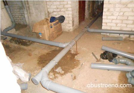
I am using terms used in the region where I happened to work as a plumber.
Often, even among professionals, the same object is called differently.
The same bed can be called a sun lounger or simply a horizontal sewer.
- Riser— a vertical pipe collecting waste from apartments located one above the other;
- Comb- indoor sewage system. It got its name in those days when plastic wiring for apartments with adjacent bathtubs and kitchens was made monolithic and really looked like a rare comb for combing hair;
- Fan pipe— ventilation outlet of the riser to the roof.
Well
Description
If storm drain is closed with lattice covers to receive wastewater, then the yard sewage well is closed with a monolithic cover, which prevents foreign objects from entering it.
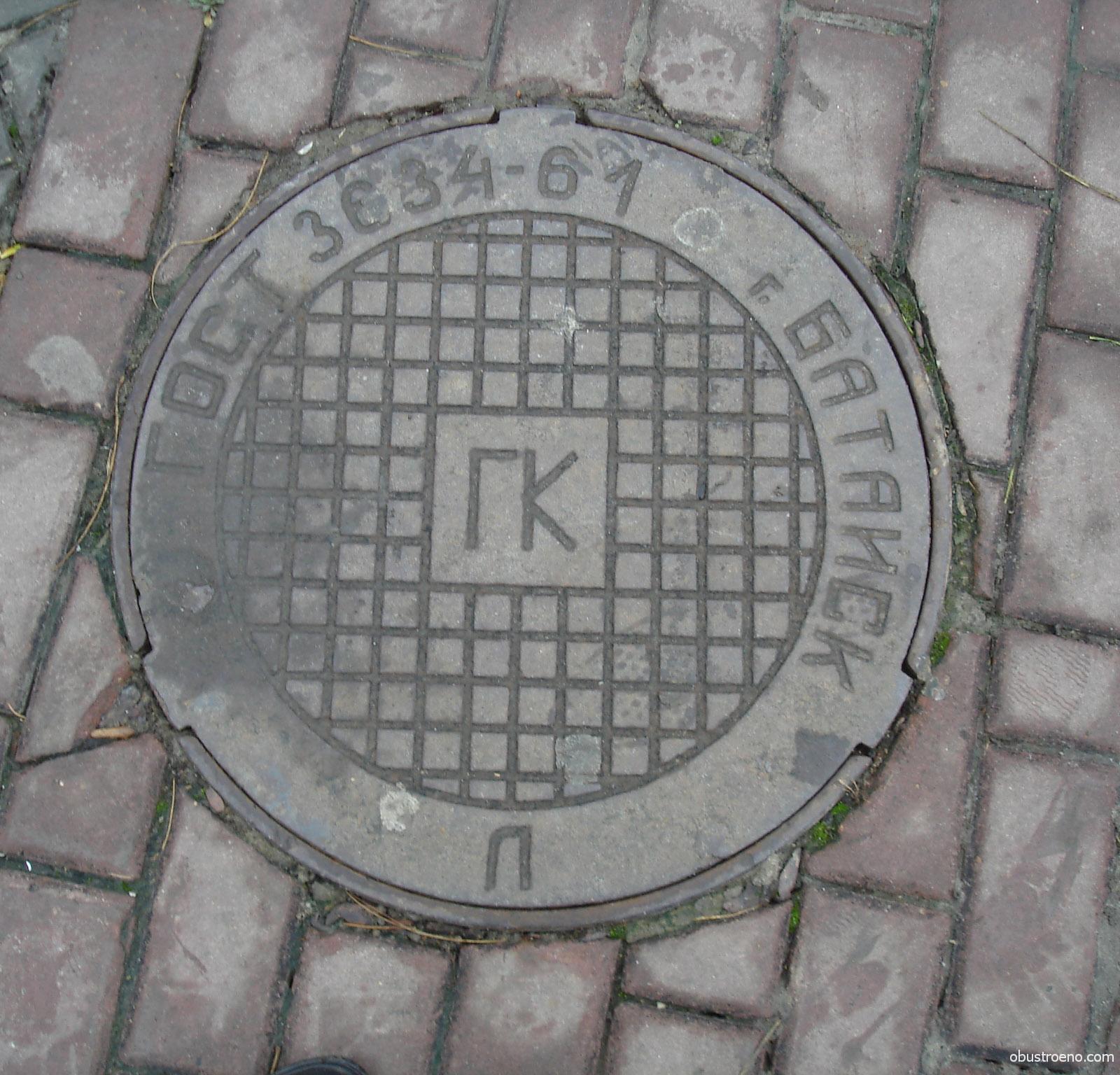
Its location is marked on the wall of the house with a designation of the form KK12, KK5, etc., in which the letters indicate the sewer well, and the number indicates the distance to this well in meters along a line drawn perpendicular to the wall with the designation.
Typical material for well walls is reinforced concrete rings with a diameter of 1000 mm. Steel brackets are fixed in the wall, allowing you to go down to the bottom level. The bottom is concreted to prevent untreated waste from entering the ground; There is usually a recess in the concrete - a tray that directs wastewater into the next well and then into the collector.
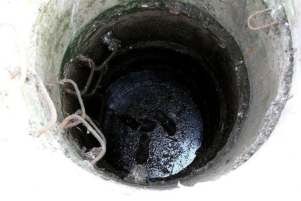
Problems
A blockage between the wells means that the entrance drains enter it, but do not go to the collector. Cleaning according to the current regulations must be carried out pneumatically:
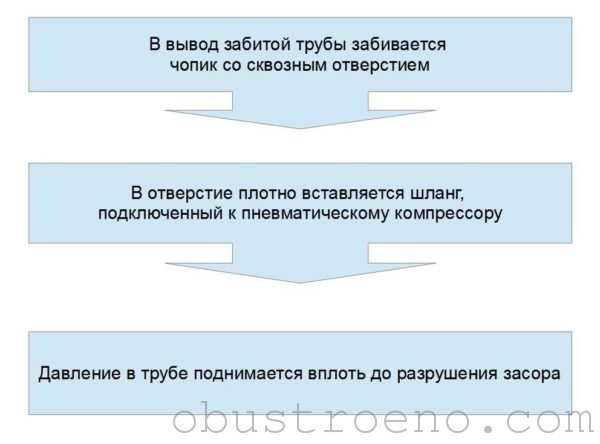
As you know, in our country not all technological operations are carried out in accordance with the regulations. Drain cleaning is no exception. In practice, sewer wire is used for it - steel wire with a diameter of 5 - 6 mm with a hook at one end and a handle at the other.
Cleaning is carried out as follows:
- The coil of wire is completely unwound;
- The mechanic goes down into the well and feeds the wire with a hook to the blockage;
- His partner pulls the wire, preventing it from folding into loops, and rotates the handle, helping the hook break the cork.

This method has four serious disadvantages.
- The walls of the well are always covered with a layer of dried sewage. A person who descends into it rises to the surface in a very unsightly form;
- The brackets of old wells are often partially or completely destroyed: wet waste fumes have a detrimental effect on the steel;
- Methane and other gases that are products of fermentation of wastewater or penetrating from the ground often accumulate in the well. By themselves they are not overly toxic; however, a lack of oxygen may well lead to loss of consciousness, and lifting an adult from a narrow shaft is more than a difficult task. The accumulation of gases in wells leads to the death of several people every year;
- When clearing a blockage, a multi-meter column of sewage hits the opposite wall of the well with such speed and force that it is quite problematic to escape from the splashes.
That is why experienced Vodokanal mechanics carry with them to accidents the simplest device - a pipe with a diameter of 32 - 40 mm, bent in the shape of a hockey stick. Its short side is inserted into the outlet from the side of the well, after which the wire is fed to the blockage through the pipe.
Outlet to the well
Description
The typical outlet diameter is 100-150 millimeters. The beginning of the outlet from the basement is equipped with a plugged tee for cleaning. The slope of the pipe is at least 1 centimeter per linear meter; changes in slope, and especially counter-slopes, are strictly prohibited, as they will inevitably lead to constant blockages.
Since the outlet is laid in the ground, quite stringent requirements are imposed on the strength of the pipes. The release is being laid:
- Cast iron pipe (including ductile iron pipe - high-strength cast iron with nodular graphite);
- An orange PVC pipe designed for outdoor use and with high ring rigidity.
Problems
The situation with the areas of responsibility in relation to the outlet is quite complicated: its blockages are cleared by housing department employees or management company, repairs and replacements are carried out by them; however, damage to the outlet due to subsidence of the well walls must be repaired by Gorvodokanal. However, every controversial case serves as a cause for friction between interested parties.

The most common exhaust problem is a clog. Its causes are:
- Rags dropped by residents into the toilet when washing floors. The rag clings to any unevenness inside the pipes and quickly becomes overgrown with other debris;
- Fat plugs. Fat from the plates settles on the walls of the pipes as the wastewater cools, gradually reducing their useful cross-section.
In this case, sewer cleaning in an apartment building is also carried out using sewer wire. It is practiced to clear blockages from both the basement and the well.

When clearing the grease plug, the hook at the end of the wire is made larger, and the wire itself, with continuous rotation, passes the blockage several times. The goal is to remove as much fat as possible from the pipe walls.
Lezhnevka
Description
The lezhnevka combines the risers of the entrance and is laid with a constant slope towards the outlet to the well of 1 - 2 cm/m depending on the diameter. In houses built after the 70s of the last century, the typical diameter of the bed is 100 mm; in Stalinka and earlier buildings you can find beds with a diameter of 150 and even 200 mm.
The pipe is laid on supports (including basement bulkheads) or hung on steel hangers, which are anchored to the ceiling. The fastening pitch depends on the diameter and material of the pipe.

With a large fastening step, the plastic pipe sags over time, forming counterslopes.
Cast iron pipes are mounted as rigidly as possible on the sockets, which prevents the destruction of their seal.
The lezhnevka is equipped with revisions or (in the case of cast iron pipes) plugged tees for cleaning:
- On turns and bends;
- Every 8 meters on straight sections.
Problems
These include:
- Inevitable blockages. In addition to rags and grease, the list of causes includes construction debris, sand and cat litter that settle in areas with minimal slope;
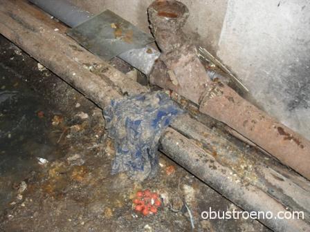
When plugs are installed and inspections are closed, blockage of the drainage pipe or outlet to the well leads to flooding of the apartments on the lower floor.
The drainage from the entire entrance begins to flow into their toilets and bathtubs.
- Leaks at socket connections (including due to destruction of sockets).
How are these problems solved?
Eliminating a leak in a plastic socket comes down to re-joining the pipes, or less often, to replacing the o-ring seal.
A cast iron bell usually has to be re-coined. How to do this work yourself?
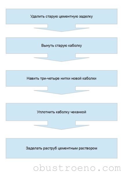
In addition to describing the algorithm of this work, it is worth mentioning a number of its subtleties:
- The easiest way to remove the old cement seal from the socket is with a chisel or a wide screwdriver. The cement is broken with a hammer and removed along the entire circumference of the pipe;
- The old heel can be removed with the same screwdriver;
- When re-minting, you can use a graphite gland instead of a heel: it is much more durable than organic fiber impregnated with oil or bitumen;
- For embossing, you can use either a specialized tool (a steel tube bent in the shape of the letter Z and flattened at the end) or a wide screwdriver;
- To seal the socket, you can use a cement-sand mixture in a 1:1 ratio or pure cement.

The blockage is cleared through the nearest tee or revision. It is advisable to clean it from top to bottom: in otherwise you may not have time to dodge the fetid stream rushing down the pipe.
Is it possible to somehow prevent flooding of first-floor apartments due to clogged drains?
Yes. It is necessary to leave the risers below the basement floor unsealed and at the same time to prevent sewage from entering the basement during normal sewer operation. This can be achieved in two ways:
- By installing an oblique tee on the riser instead of an inspection;

If the riser is clogged, the drainage will flow through the tee outlet into the basement. Its flooding is also not a gift, but it’s still better than a flood in the apartment.
- Replacing the inspection cover with a homemade one, equipped with a bend directed upward at an oblique angle.
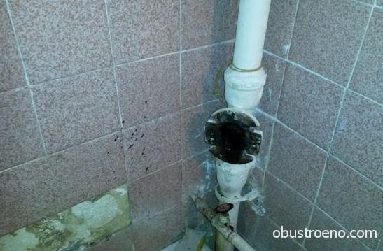
Riser
Description
The typical diameter of a sewer riser is 100 mm. However, there are no rules without exceptions:
- In post-war houses I have seen risers with a diameter of 150 mm;
- In small-family houses of some layouts, kitchens are equipped with a separate riser with a diameter of 50 mm.
The riser is laid with socket pipes with the sockets oriented upward; At the floor level, tees and crosses are installed to connect the combs. Cleaning inspections include:
- In the basement, half a meter - a meter above the connection with the bed;
- On the extreme floors;
- In buildings of five floors and above - every three floors.
At the top, the riser extends beyond the roof and ends with a waste pipe communicating with the atmosphere.
Problems
There are four main problems with sewer risers.
Blockages
A clogged sewer in an apartment building in most cases is a consequence of violation of the rules for using the sewer. The riser is clogged by foreign objects that have gotten into it from apartments or from the roof.
The blockage is cleared from top to bottom through the nearest revision.
For cleaning, we use the already familiar sewer wire. Strong and large objects that fall into the sewer require special measures: cleaning is carried out from the roof through the drain pipe and comes down to breaking through the blockage with a crowbar lowered on a rope.
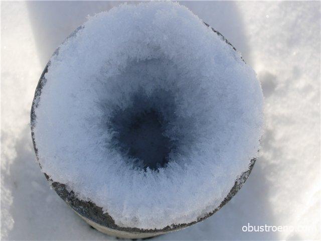
Ventilation failure
In winter, the fan outlets of the risers often freeze: moist evaporation settling on the walls gradually reduces the clearance to zero. The thrust in the riser does not disappear anywhere; As a result, sewer aromas begin to saturate the apartments on the upper floors through leaky connections to plumbing fixtures and water seals damaged by the vacuum that occurs when toilets are flushed.
The problem is solved:
- defrosting the riser. For this purpose, it is enough to pour a bucket of hot water into the drain pipe;
- insulation of the drain pipe, preventing the freezing of vapors on its inner surface.
Noise
Plastic pipes have one unpleasant feature: they make the slightest noise in the riser audible. As a result, you hear the neighbors above draining water, the noise of the wind in the drain pipe, the sound of dripping from a faucet that is not fully closed, and other annoying noises.
The noise problem can be solved in two ways:
- Installation of so-called silent pipes. They differ from conventional ones by the addition of mineral filler, increased thickness and variable density of layers;
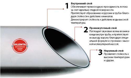
The price of a silent sewer pipe is 3 - 4 times higher than the cost of a conventional PVC pipe.
- Soundproofing the riser with any roll insulation, foam shell or a gypsum plasterboard box constructed around the riser, wall panels or lining.
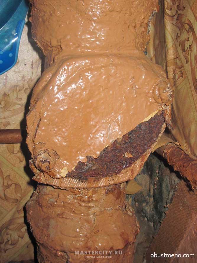
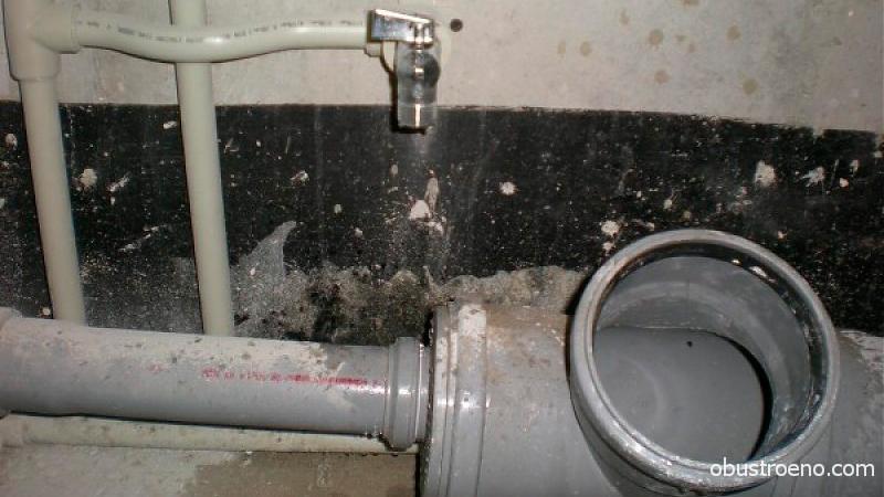
Violation of tightness
Its typical cause is the destruction of the cast iron pipe socket or coupling under the weight of the pipe and due to corrosion.

The photo shows a destroyed cast iron coupling.
The defective area is replaced using a sewer coupling and a compensating pipe:
- Two cuts are made above and below the destroyed bell. The distance between them should be equal to the length of the compensator;
- The compensating pipe is pushed all the way onto the upper pipe;
- A coupling is put on the down pipe;
- The compensator settles into the coupling socket;
- All connections are sealed.
To repair a cast iron riser, you can use a plastic fitting of the appropriate diameter.
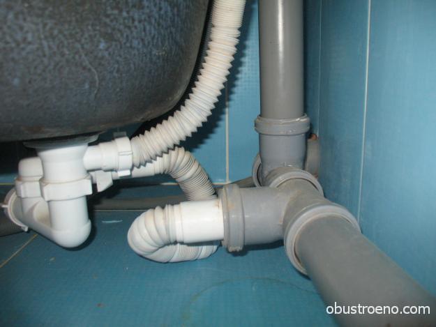
The surface of cast iron pipes is first cleaned of layers and rust.
Comb
Description
A horizontal pipe collecting apartment wastewater from several plumbing fixtures is laid with a diameter of 50 mm. An exception is the toilet: the outlet for its connection should not have a smaller diameter than its outlet.
The slope of a comb with a diameter of 50 mm should be 3.5 cm/m. For fastening plastic pipes clamps and clips are used on the wall; The attachment points should be no more than 40 - 50 cm apart from each other.
In the absence of clamps and clips, I laid the pipes on 6 mm thick wire driven into holes drilled in the wall. The ends of the improvised brackets were bent into a vertical position.
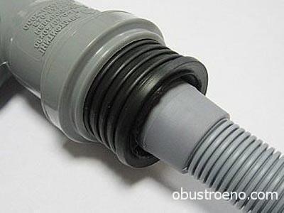
The connection of the comb outlets with plumbing fixtures is made airtight to avoid the appearance of odors. For sealing, standard sewerage seals or rubber cuffs are used.
Problems
Plastic indoor sewage systems are characterized by only two problems:
- Smells. Their reason is in leaky connections of the comb with sinks and washbasins. To combat odors, it is enough to seal the joints with cuffs. As a temporary measure, they can be wrapped with regular tape;
- Blockages. Typical problem clogged 50mm comb - grease deposited on the walls of the pipe that gets into the sewer when washing dishes. The blockage can be cleared with a cable followed by washing hot water; however, it is better to simply disassemble the sewer and shake out all the accumulated debris from the pipes.
Cast iron combs of old houses often leak along the sockets. I described the method of minting cast iron sockets above.
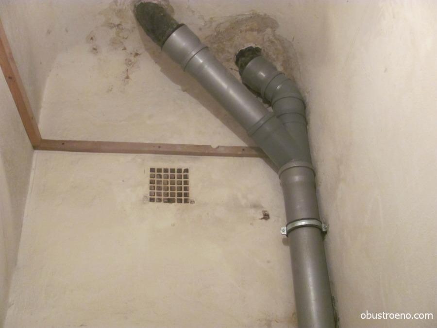
Fan pipe
Its diameter in general should be equal to the diameter of the riser; however, in new houses it is common practice to combine two to four risers with one outlet leading to the roof. I have already touched on the problems and their solutions in the “riser” section.
All you need to know about the sewer drain is that it is necessary for the normal functioning of the sewer system. The practice of replacing a drain pipe with a vacuum valve is not a complete solution. The draft arising in the riser in the absence of ventilation transports all odors to the nearest leaky connection on one of the upper floors.
![]()
Exiting the riser to the roof is not at all an extra detail of the interior.
Prevention
I have written a lot about sewer problems, but not a word about how you can avoid them.
The rules and regulations for sewerage in an apartment building, which are mandatory for all residents, are simple and understandable.
- The toilet is used only for its intended purpose. Food waste, construction waste, thick paper, garbage are disposed of in other ways;
- The outlets of bathtubs, showers and sinks are equipped with grates or mesh to prevent foreign objects from entering the sewer system;

- Unauthorized transfer and change in the diameter of risers, benches and outlets to the well is strictly prohibited. If you want to change their configuration, contact your local housing organization for approval;
- Before you pour water into the toilet after washing the floors, take the time to make sure there is no rag in the bucket.
Will help get rid of fatty plugs in the comb simple recommendation, which, alas, is often ignored by the rules for using sewerage in an apartment building published in the media. Wash dishes with hot water (literally on the verge of a comfortable temperature). I have long noticed that problems with fat deposits begin in the summer, when the hot water temperature drops to its minimum.
Conclusion
I hope that I was able to answer all the questions related to the sewage system of an apartment building. As always, the video in this article will offer additional information. I would appreciate your additions and comments. Good luck, comrades!
July 7, 2016If you want to express gratitude, add a clarification or objection, or ask the author something - add a comment or say thank you!
Play poker, Royal Flush online-poker-besplatno.com two pairs play All in.