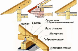
Roof support unit. Layered rafter system: schematic diagrams and installation
The layered rafter system can be a spacer or non-spacer structure. Whether the rafters will push the walls or not will depend on the correct choice of support nodes and articulation of the rafter legs; it is necessary to provide various measures for them to intercept the thrust or not.
On the design diagrams, circles are drawn at the structural nodes, meaning swivel joint. The hinges are connected with claws to conditional supports, along which the degree of freedom of the assembly can be visually represented. A hinge with two legs embedded in the support assumes that the node is motionless, but the beam can rotate in the hinge, that is, the node has one degree of freedom - rotation. A hinge with legs standing on a sliding support or slider shows that the assembly has two degrees of freedom - the ability to rotate the beam and horizontal displacement. Three degrees of freedom of the node allow horizontal, vertical displacement and rotation; such a node is simply drawn as a circle and can be cut into a rod representing a beam. If the node is embedded in a beam, then it is called a split beam, that is, the beams located to the left and right of the hinge can, with some assumptions, be considered as separate elements. If a circle (hinge) is drawn under a beam, then the beam lying on it is called continuous. The three-degree-of-freedom hinge embedded in the beam, in many cases, makes it an instantly variable system, that is, a rather unstable structure. A node with a zero degree of freedom means rigid pinching of the end of the beam and prohibits it from any displacement: horizontal, vertical and rotation (Fig. 19).
Rice. 19. Examples of schematic representation of nodes
In the calculation diagrams, other schematic representations of nodes may be used, but they are all generally understandable, and if ambiguities suddenly arise, you just need to mentally imagine in which direction the node can “go” when a load is applied to it. The transverse dimensions of the beams relative to their length are small, so the beams (rafters, etc.) are drawn as rods, and the load in them is distributed as if only along the longitudinal axis of the element, and the calculation of the entire structure is carried out for the rod diagram.
It should be noted that the words: horizontal displacement and rotation do not mean at all that, for example, a slider - a unit with two degrees of freedom - moves arbitrarily in the horizontal direction. In fact, this node is quite well fixed, but allows the end of the beam to move due to load, temperature and humidity changes without excessive development of internal stresses in it. This unit simply does not transmit thrust, and rotation when bending the beam is possible only within standard limits. The slider will truly crawl (forgive the tautology) only under loads exceeding the maximum permissible. The word “hinge” also does not need to be taken literally. Yes, the ends of the beams can be connected with a bolt or an actual specially designed hinge, but most often it is a regular nail connection. For example, you can take a board and nail it at one end with 3-4 nails, say, to wooden wall. Nothing prevents us from taking it by the other end and calmly turning it to a certain angle. In this case, the nail fastening acts as a hinge. However, if the number of nails is increased and they are designed for a load that does not allow shearing (bending), then rotation becomes impossible; here we get a beam with a pinched end, but when the load exceeds the calculated one, the node again becomes a hinge. Therefore, it is very important to initially determine the load under which the system will operate. Since the excess of the actual load over the calculated one leads to a change in the operation pattern of the units and destruction of the entire structure.
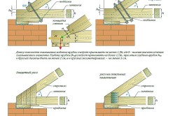
The connections of layered rafters related to various schematic representations of nodes are presented in Figure 20.
Rice. 20.1. Knots for supporting rafters on purlins and mauerlat. Hinge with one degree of freedom (rotation only) fig. 20.2. Knots for supporting rafters on purlins and mauerlat. The slider is a hinge with two degrees of freedom (rotation and shift) fig. 20.3. Supporting unit for rafters on the purlin. Hard pinching
Depending on the problem being solved when designing a roof, the nodal joints of the rafters may differ from those presented in Figure 20. The main thing is to design in nodes with two degrees of freedom: rotation arising from the bending of the rafters and shift in the horizontal direction. And in nodes with one degree of freedom - rotation of the rafters. As a rule, the shift of the top or bottom of the rafters is ensured by horizontal notches, and the shift is limited by the rafters resting on each other and/or on the joining element: the mauerlat or purlin.
Let's try to explain the principle of fastening the rafters using an example. We can all easily imagine an ordinary ladder. The staircase is just like a staircase, nothing special: two poles (strings) and transverse sticks-steps. Let’s mentally put such a ladder against the wall, and for the purity of the experiment, we’ll minimize the friction forces by pouring oil on the floor and wall. What happens if you load a ladder and climb on it? The stairs will collapse. It has two degrees of freedom in the lower and upper supports. In the lower one, it has rotation and horizontal displacement, in the upper one it has rotation and vertical displacement. What needs to be done to make the ladder stable and support the load (person’s weight)? All you need to do is deprive it of one (out of four) degrees of freedom: horizontal in the lower or vertical in the upper support. In other words, you need to secure the bottom or top of the stairs. We get a stable and stable system. You can come up with a thought experiment with a ladder yourself, placing it in various situations, for example, if the ladder is long and rests on the wall from above, with strings with horizontal cuts or without cuts. How will she behave? Such brainstorming helps in understanding the work of layered rafters with different ways support, in which it is not at all necessary to imagine the vectors of forces and degrees of freedom of the nodes, but you just need to predict whether the ladder will roll under load or remain motionless.
ATTENTION! Fastening Mauerlat is sometimes ineffective due to the fact that anchor bolts placed incorrectly in reinforced concrete stiffening belt or in mauerlat beam executed incorrectly holes for them.
In such cases the nuts are screwed on on bolts with constriction, node becomes unreliable and quickly is destroyed.
For fastening Mauerlat with rafters and wall structures for this purpose, sometimes instead of a coupling bolt use twisted wire(node-13 and node-1).
Roofs combined with ceilings, in most houses they have such a width that floor beams rely not only on external load-bearing walls, but also on middle load-bearing wall.
The design will work in accordance with the design only if and along an intermediate load-bearing wall floor beams connected to each other by reinforced concrete stiffening belt(see above node 15 pos. 2 and below node 16 pos. 2-a).
Destruction of house walls with perception roof rafter spread shown in Fig. 1.
This is often neglected, overlap does not fulfill its functions, and the roof is coming apart(Fig. 1).
NOTE: Construction roof trusses, combined with the ceiling, there, where they don't take into account role bearing capacity attic floor, very dangerous.
Frame system integrity when constructing roofs without a monolithic reinforced concrete belt Mauerlatov must be ensured its fastening corner connections.
Figure 1-1 schematically shows 2 device options horizontal connections in the plane of the roofs For Mauerlatov.

with a span between load-bearing walls of up to 5 m, it is allowed to install rafters along transverse purlins, so called hanging rafters. For them, instead of horizontal connections, they perform wind braces(Fig. 1).
Preferably this location of main supports for rafter legs, which leads to symmetrical and balanced solution rafter system.
Symmetrical roof rafter system shown in diagram 6.
NOTE: It happens that tightening the frame system trying to replace prefabricated reinforced concrete floor beams, which Designed for bending work only. Prefabricated reinforced concrete beams used as puffs in that case, if their ends are firmly fixed in reinforced concrete floor rigidity belt(steel reinforcement connections, welded to the structural frames), and the axis matches exactly with direction active forces.
Right and wrong Mauerlat fastening shown in the figure is node-16.

ATTENTION! If in the perpendicular direction to the beams between them and the elements flooring there is no such strong connection, which would ensure the perception of loads, then communication breakdown And the roof is collapsing.
NOTE: When docking Mauerlat with the house structures (node-17) should be horizontal position is maintained Mauerlat soles Not only with walls, but also rafter foot soles with support platform on the Mauerlat.
Incline support platforms(including Mauerlatov) leads to the appearance of thrust and sliding rafters and roof generally. That's why Mauerlat system should represent closed horizontal frame, fixed along the alignment axes on the load-bearing walls of the house.
ATTENTION! In a reinforced concrete element, for example, you can, if necessary, without changing size and shape this element "add a couple of rods". When it comes to wood, then, on the contrary, the slightest change in any detail in design rafter system Maybe require all sizes to be changed!
2. Preparing walls for roof installation.
Before start of laying out brick cornices with overhangs mark position of the architectural element. Then install moorings and put it on the wall first row brick required profile.
Rows masonry cornices perform "poke" from whole bricks. Wherein overhang of each row of masonry no more than 1/3 the length of the brick, and the general take out unreinforced brick - no more than 0.5 wall thickness(item 1 node 13).
Cornices with common offset more than 0.5 wall thickness should be arranged made of reinforced brickwork on brand solution not lower than M-25. Cornices from prefabricated reinforced concrete elements - they are also anchored in the masonry walls.
Distance from the top attic floor to the support roofs should be done:
- to the bottom of the mauerlat - no more than 500 mm;
- to the bottom of the middle bed - no more than 400 mm.
If wall construction ends strengthening brick eaves overhangs(node 13), then Mauerlats secured to pinched masonry plugs.
In brick walls antiseptic or tarred traffic jams(node 1) pinched in brickwork cement solution M-100 in steps 1…1.5 m (equal to the rafter pitch, which depends from load on the roof) or lay down on a monolithic belt along the perimeter house walls with embedded parts for mounting mauerlat and lazney.
Subsequent work is carried out after setting with the solution plugs with masonry(in 2-3 days). It will be more reliable to fasten the roof if these plugs are pinched into the wall in advance during its laying.
If the overlap has already been completed (as in our example - from reinforced concrete slabs), then covered antiseptic and tarred underneath Mauerlats(item 3 node 1) are stacked to carrier brick wall Houses over two layers of roofing felt And attached to pinched into the wall wooden traffic jams(item 2 node 1).
NOTE: If the walls are ending without amplification masonry cornice with overhang, That masonry head walls needs to be secured monolithic belt. In monolithic belts(node 16) jammed screw fittings install with the spacing of the rafter legs according to the project.
Mauerlats and other parts rafters, in contact with a monolithic belt, should also be insulated with gaskets from rolled waterproofing materials (two layers of roofing felt) - this will protect them from possible dampness and rotting.
In small outbuildings with span between load-bearing walls up to 5 m it is allowed to install rafters along transverse runs, so called hanging rafters.
The attachment point for hanging rafters to the walls of the house is shown in Fig. 1-2.
Suspended rafters mounted on a wooden frame from more lying (Mauerlatov) along the perimeter of the walls. By runs can also serve wooden flooring of the house during installation hanging rafters.
Frame for purlins secure on the wall structure using wooden corks(Fig. 1-2 item 3), pinched into the masonry, or using anchor bolts (node-15 item 3) monolithic belt around the perimeter of the walls for the future roof with built-in with tightening fastenings under the Mauerlat or bench.
Styling roof elements in the direction covered span should execute in compliance with the dimensions established by the project the depth of their support on supporting structures and gaps between mating elements.
3. Installation of the Mauerlat under the roof rafter system.
Installation elements Mauerlats, roof trusses(beams) supported on the walls should perform - combining risks, fixing geometric axes of the lower chords of trusses (beams), with alignment axle marks on supports.
Mauerlats and others rafter parts, touching with masonry, isolate gaskets from rolled waterproofing materials. This will protect them from the possibility of dampness and rotting.
ATTENTION! To avoid displacement roofs windy ends layered rafter legs, stacked on the Mauerlat, connected to the Mauerlat corner brackets. And after one rafter leg put twist from wire Bp-I d=4...6 mm in 2 threads connecting the rafter leg with the wall masonry (node-1) through ruffs or crutches.
Crutches for twisting score in the masonry wall on distance 300 mm below the wall edge under the Mauerlat. Support nodes rafter leg made of lumber on a mauerlat shown in Fig. node-1.

One support rafter leg is Mauerlat(item 3 node 1), laid level on antiseptic wooden walls clamped into the masonry traffic jams(item 2 node 1), and other end rafter leg rests for a run, stackable on racks or lie down(item 3 node 2).
Sill fixed on traffic jams, pinched in the masonry internal load-bearing walls, laid out above the level of the external walls stone house. Being laid such sill(like the Mauerlat) along the entire length interior wall home, which also relies roof truss system. Support nodes rafter leg made of lumber on a bed shown in Fig. node-2.

ATTENTION! In all cases roof trusses (beams) should install in compliance with one-way direction deviations from the straightness of their upper chords.
Mauerlats in buildings with external walls made of lightweight masonry, and also in case frequent arrangement of rafters (with a pitch of rafter legs less than 700 mm) arrange for continuous.
On solid masonry walls when walking rafter legs more 700 mm Mauerlats can be arranged from short pieces 500-700 mm long secured with reinforcing ties on a monolithic belt(node 22 and node 23).
With pitched roofs under construction with span between external walls up to 5 m rafter system represents rafter legs from whole beams, boards or logs, relying for two mauerlats, installed at different heights. Installation Mauerlatov for roofs in extensions and for pitched roofs detached buildings is shown using the example of node 22 and node 23.

Constructive compound wooden elements in one plane from beams and logs performed using hinge joints. Compressive forces are transmitted by direct support and by additional connections. The hinged joint connects designs mauerlats, purlins and rafter legs. The joint is attached one M-16 bolt.
For perception tensile forces in the rafters apply additional connection elements(For example, screw nails or screws).
More information about the arrangement of rafters, fastening points and the distance between them is in the following sections of the site.
- Brief information about the structure of the rafter system and its design
- How to install and secure rafters
- How to attach the Mauerlat to the rafter legs
- We fasten the rafters with the Mauerlat
Installing rafters for the roof and attaching the rafters to the mauerlat is a very complex and responsible job. At the same time, the strength of the roof depends on small details, however, many do not understand this, which often leads to unpleasant (and sometimes tragic) consequences. Since the rafters are the main load-bearing structure of the roof, the connection of the rafters with the power plate must be as strong and reliable as possible, since the further safety of the work and the strength of the entire structure as a whole largely depend on this. How to attach the rafters to the mauerlat is described below.
Brief information about the structure of the rafter system and its design
The rafter system is the name given to the beams on which the roof rests, and the rafters themselves rest on load-bearing walls around the perimeter of the building. At the same time, a mauerlat is often created under them (the so-called beams on which the rafters rest). Rafters can differ significantly in their appearance, materials used and their quantity. They also differ in the permissible maximum load that they can withstand. At the same time, the rafters determine the shape of the roof and often the roofing material

To create a rafter system project, it is strongly recommended to contact a specialized architectural bureau, since this is a very complex job. For correct calculations during design, it is necessary to calculate the maximum wind load (even if the winds in this area are not frequent or strong), the amount of precipitation in winter and summer, know the weight of the roofing material with sheathing underneath, etc. It is on the basis of such calculations that the thickness of the load-bearing walls of the perimeter of the building is determined. If the calculation was made incorrectly, then various unpleasant consequences are possible, from deformation of the roof to “separation” and collapse of load-bearing walls.
Return to contents
How to install and secure rafters
Currently, there are several fastening options. The types of fastenings differ only in the materials used for fastening. It can be done:
- stiletto heels. They are made of metal, fastening is carried out at the joint with a pair of reinforcing pads;
- nails. Inexpensive staples can also be used. They secure the legs of the rafters;
- nail plates. They are a galvanized strip that has a number of through holes for nails (sometimes there may be several rows). This allows you to create a high-strength connection.
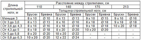
There is a division of the legs of the rafter system into layered and hanging. The first ones are used in the construction of 1-2 pitched roofs, in buildings that have load-bearing walls in the center. Here the main (ridge) beam is strengthened with the help of columns or supports (racks can be used). The maximum permissible length of a beam without supports is 9 m; for a 12-meter beam, two support points are installed, and for a beam 13 m long, three. The support unit must be strong and reliable. Columns should be poured from the foundation, and beds should be made under supports or racks. The second type of supports is less reliable and is used only on small buildings and areas.
Next, choose methods for attaching the rafters to the mauerlat and ridge beam. So, for layered rafters, spacer or non-spacer types are used. Another design option is not subject to pressures that push the walls from the impact of the building supports. When constructing a spacer system, rigid fasteners are used that run along the pediment. In this case, the main loads are borne by the supporting structures and columns of the building.
In this case, the rafter systems are attached to the mauerlat using a special “tooth”, which is a support beam. Next, the rafter structures rest with their upper parts against the opposite ones.
![]()
The rafters and mauerlat must be attached to the special structure of the house. So, if the walls are made of brick, special embedded elements are provided during the masonry process. For walls made of other materials, it is necessary to make a concrete screed in which backfills are provided. A welded steel frame can also perform this function. In the latter case, the frame is attached to the walls using anchors.
Frames can only be used for small buildings. If the building is large, then the only way out will be to pour a reinforced concrete screed, inside of which there will be gutters for laying the mauerlat. In this case, the Mauerlat itself is attached with anchors to the ends of the gutters. This type of construction is necessary for buildings made of foam concrete blocks, cinder blocks and other not very heavy materials.
Return to contents
How to attach the Mauerlat to the rafter legs
The joining of the Mauerlat and the rafter leg is carried out based on what the Mauerlat is used for. If the Mauerlat is used as a support structure for the legs of the rafters, then in this case the upper end is fastened with a ridge run, fastening the rafters to the walls, using the “sliding support” method. If the lower ends of the rafters and the ends of the legs are attached to the mauerlat (or to other single beams), then it is necessary to use “sliders”, and at the top the rafter system is connected with nails and bolted joints.
Separately, it is worth considering the fastening of the rafter system with a Mauerlat for non-thrust structures. To do this, it is necessary to correctly make the fasteners using “sliders” (several pieces on each beam). It is worth noting that there should be no stops (auxiliary) on the lower part of the rafters. In this case, the upper part, which abuts the other rafters, must be connected to the stop with special pads. This method of fastening can lead to pinching of the rafter leg or to some rotation of it (this is possible if one of the ends rests against the purlin on the ridge beam).
Another method of fastening is rigid fastening, in which the lower ends of the rafters are pinched with a Mauerlat. In this case, a support strip is used (or a cut is provided) so that the upper parts of the rafters rest against the ridge purlins, and to fix them at the top, a horizontal notch is made or secured with “sliders”. This type of fastening allows for some possibility of vertical rotation at the junction point.
In order to securely fasten beams to rafters, as well as to prevent the legs of the rafters from sliding, it is necessary to correctly apply three main fastening methods. These include a tooth with a special spike, a tooth with a stop, or a stop in the lower parts of the beam floors.
Layered rafters, resting on the wooden frame of the building walls (mauerlat, rafter beam), or on the upper crown of a wooden frame, are used in buildings with short spans. What are the elements of their design and the order of the device - later in the article.
The maximum span size that can be covered by a layered rafter system without internal supports is 6-6.5 m. If there are load-bearing structures inside the building - walls or columns, racks can be installed on them.
By tightening the rafter legs with a crossbar, the span can be increased to 8 m, using one support - up to 12, and using two supports - up to 16 m.
In individual housing construction, larger spans are rare, so layered structures can be used in almost any private house.
Since the rafters are supported here on the mauerlat (in a wooden building, its role is played by the top row of the wall), the node of this connection is very important.
It is impossible to lay rafters directly on a stone wall, as this will lead to the formation of condensation and rotting of the wooden parts of the structure. The Mauerlat itself also needs insulation.
Important information! Waterproofing devices require not only the support of the rafters on the mauerlat, but also any junction of wood with stone or metal structures. For this, a double layer of roofing felt or other similar material is used.

Construction details of layered rafters
1-rafter leg
2-mauerlat
3-twist
4-external load-bearing wall
5-notch
6-leg
7-internal load-bearing wall
8-waterproofing
How to properly fasten the rafters to the rafter beam is very important point when installing a layered roofing system. First of all, the Mauerlat itself must be securely fastened - for this they use either metal pins concreted into the wall to a depth of at least 40 cm, or bolts secured in the same way.
These can also be twisted wires F of at least 6 mm, laid during the construction of walls at a distance of no more than 3 rows of masonry from the top edge.
Sometimes also used. The Mauerlat itself is a beam with a side of 140-160 mm. The same requirements apply to the beam - a beam running along the internal load-bearing structures.
In house construction, wooden layered rafter systems are used, since the use of metal or reinforced concrete elements here is very difficult to implement, if not impossible.
Therefore, to fasten the rafters to each other, as well as to all types of support beams and other parts, various carpentry joints are widely used - a tenon, a tooth, a frying pan.
Since in a layered system the structure bears the pressure of itself and the roofing pie, all these loads should be taken into account before correctly laying the rafters.
Installation of roof load-bearing structures on damp areas requires special attention. wooden log houses, where shrinkage has not yet occurred.
Important information! The shrinkage coefficient of a log house made of logs or timber is 4-6%. If the height of the walls is about 3 m, after a year it can be reduced by 10-20 cm, which can negatively affect both the inserted joinery and the load-bearing elements of the roof. These figures are included in the project initially (the dimensions of the house are given in two versions - initial and “post-shrinkage”)
Hanging rafter systems can be used. Otherwise, the problem can be solved in several ways: wait until the shrinkage ends, or install rafters with sliding supports, or install screw jacks (shrinkage compensators) under all supporting structures.

Rafter system fastening details
1-roofing material
2-waterproofing
3-sheathing
4-filly
5-hemming boards
6-twist from a rod
7-rafters
8-bolts
9-floor boards
10-thermal insulation
11-beam
12-staple
13-strut
14-ridge beam
15-mauerlat
The disadvantages of the first method are clear - it is a long wait. The latter is also not optimal, since it will require high-precision manual operations. Sliding mounts are virtually self-adjusting and have an added benefit.
Wood is a living material, and even after shrinking it will “breathe” constantly. Of course, the deformations will not be so significant, but they will occur constantly - and the sliding structure perfectly compensates for them.
It looks like this: a corner is attached to the Mauerlat, with a block stuffed at the required angle, or a cutting of the required shape, one of the shelves of which is bent. A working relief plate is threaded under the bend.
Since the direction of sliding will be directed outward, it is better to fix the plate on the rafter in such a way that the greatest possible distance for free movement remains towards the ridge of the building.
When purchasing a sliding connection, you should remember that their working size (the distance between the supporting pads of the plates) may vary.
It is selected depending on the planned degree of shrinkage and should be no less than it (please note that the actual amount of shrinkage will be distributed over the rafters of both slopes).
Important information! It must be remembered that resting the rafters on the rafter beam is not the only movable unit of this structure. The ridge should also include a hinge joint of one type or another. Layered rafters can be joined end-to-end using metal plates, but it is necessary to leave a sufficient angle at the ends so that when the rafters converge, they do not rest against each other. The second option is to connect the rafters overlay, using a through hole in both legs, through which one bolt passes.
Layered rafter structures
Any rafter system where the upper fastening point is hinged, and the lower one has a hinge and a floating connection (slider, as in the version above) is classified as non-thrust.
In them, the bursting loads are not transferred to the Mauerlat, and through it to the walls. Expansion rafters - a scheme where the ridge connection is made rigidly, and the support on the Mauerlat is hinged, for example using a “tooth” connection, and it transmits the pushing force to the walls.
In essence, this is a hybrid scheme that combines layered rafters and hanging ones, especially when the horizontal scrum is low in the layered ones.
At the same time, due to the fact that the force from the weight of the roof is taken directly by the rafter legs, connected end-to-end, and working in bending, the ridge beam practically does not work, and becomes an optional element of the system.
Important information! All bolted connections are made through pre-drilled holes with a diameter 1 mm less than the diameter of the bolt or stud. If you make them too large while the part is free-swinging, the power plate may be damaged. This is especially true for the spacer scheme.
Depending on which connections are made rigid and which are hinged, different rafter options will work differently.
Under normal, unloaded operation conditions, as a rule, all elements experience approximately the same load.
However, in winter time, with snow falling, different weights tend to be applied to each of the slopes.
If the racks are poorly secured or installed incorrectly, this can lead to a shift of the roof towards a more loaded slope.
This is especially true for a non-thrust design, where there is the possibility of displacement. The problem is solved by reliable fastening of the ridge beam against longitudinal shifts.
Procedure for installing rafters
- If lumber of the required length or thickness is not available, it is obtained by nail splicing or self-tapping screws
- A rafter template is made, if the design uses racks and struts - also samples for them
Important information! It should be remembered that in hip roofs (which usually have 4 slopes), the length of the rafters located at the junction of the slopes will decrease from the ridge to the mauerlat.
This is called a diagonal rafter leg (it is also called a slanted leg). Due to enough complex design of such a roof, here templates are prepared only for the elements of the main slopes, the rest is assembled and adjusted on site.

- After this, struts, trusses and other supporting parts are installed
- If the project includes horizontal rafters (which to a certain extent makes the schemes of layered rafters and hanging rafters similar), then at the next stage they are attached
- Depending on the length of the rafter legs and the roof structure, plumb lines are arranged. For most buildings the roof must extend beyond external walls no less than 50 cm to prevent precipitation from entering the lower part of the supporting structures. If the rafters are supported by a tooth or tenon on the mauerlat, a special extension element - a filly - is nailed to their lower edge on the side
- If fillies are installed, they are sheathed with continuous wooden sheathing around the entire perimeter of the building
At the next stage, the layered rafters are sheathed with lathing themselves - and the installation of a roofing cake from the selected materials follows: vapor and waterproofing, insulation and roof covering.
Layered rafters can be spacer or non-spacer. Rafters in a non-thrust system work in bending, and therefore do not transmit thrust forces to the walls.
Nodes
Mounting the Mauerlat
The main components of the rafter structure are located at the points where the rafters are attached to the mauerlats lying along the walls (as shown in the figure). It is important to place the Mauerlat perpendicular to the wall and the floor belt, and not at the angle of the roof. The Mauerlat is fastened using anchor bolts, both to the floor beams and to the roof rafters.
Upper rafter fastening
The roof ridge is held in place thanks to the structural wooden element - ridge girder made of timber. There are two ways to attach rafters to it: 1 – with trimming, 2 – without trimming the rafters.
In the first case, the rafters are on the same axis and are cut to the cross-section of the ridge girder and for joining joint to joint. Then they are firmly clamped using anchor bolts and a metal plate.
In the second case, the rafters do not need to be trimmed, and they are overlapped (side by side). Then they are also clamped with a metal plate on both sides.
Bottom rafter fastening
Supporting the rafter leg with trimming. To make the attachment point for the rafter leg and the mauerlat from a log reliable, it is necessary to cut the logs in the right place both in the mauerlat and in the rafter leg. And to attach the filly, you will have to make another trim in the rafter leg, 20 mm thick.

Lathing
The sheathing pitch is usually equated to 300 - 350 mm, since the roof will be attached to it at equal intervals. The sheathing bars begin to be laid from above, from the ridge. The sheathing is not placed on the cornice; there is a special cornice shield that is supported on the filly.