The best color schemes. Homemade color music from LEDs
Homemade color music
Homemade color music in the interior of your own car will be of interest to all lovers of beautiful disco music. Making it with your own hands is absolutely easy.
Color music at home can be quickly and easily assembled if you know some of the nuances of the circuit and its correct installation.
Color music schemes in cars
A large number of homemade color music schemes are published on amateur radio forums. Some of them are intended only for experienced, others for beginners.
In principle, all schemes are built according to the same principle, which is recommended to be understood so that the assembly no longer represents something impracticable and very complex.
Simple scheme
Even a schoolchild can assemble color music using this scheme, because it consists of only one transistor. Its name is KT815G.
This color music can be assembled using diodes borrowed from a simple flashlight.
Everything is done as follows:
- We divide the LEDs that we removed from the flashlight in half;
- We find a suitable box in which we will assemble our circuit. In this case, instead of a box, a rectangular plastic box from used shoe polish is ideal;
- We take out the switch. It will change the light-music mode to simple lighting.
Note. The LEDs will flash with bass and the higher the volume, the brighter they glow. As for the channels, two are enough, not connected to the speaker.
- The power source in our case will be three AA batteries;
- All that remains is to put the homemade color music in the trunk and enjoy the effect.
Complex circuits
They will allow you to create more professional schemes from the user's point of view.
First version of the scheme
It is assembled on five diodes. All of them are five millimeter and 3 V, have clear lenses. The transistor used is KT815 or KT972. Its task is to strengthen and act as a key.
Everything is done like this:
- Power is supplied from 2 1.5-volt batteries;
- There are respectively two inputs for music: X1 and X2;
- In place of LED3 we install a red diode, the remaining remaining pairs will be blue and green;
Note. As a result, we get a very successful color and music scheme. The LEDs glow very effectively to the beat of the music, the circuit consumes little current, and low frequencies are reproduced simply superb. You just need to be careful: the LEDs may not be able to withstand loud music and burn out.
Second version of the scheme
We find the KT817 transistor, wires, headphone plug and SD tape.
Started:
- We solder the transistor according to the following scheme;
- Then the CD tape is added and everything is moved to the luggage compartment of the car.
Light music from garlands
A completely successful solution that will require the use of light bulbs from New Year's garlands:
- Garlands (see) need to be collected together in several pieces and secured with electrical tape;
- Make an adapter to connect to the head unit and connect the wire.
Note. The circuit in this case will involve eight twisted pair conductors, which transmit the signal from the contacts of the control unit to the color music control unit.
Color music from LEDs
An original scheme for making beautiful color music. In this case, you need a housing made of plexiglass.
Let's get started:
- We select two plates measuring 5x15 cm and two square plates 5x5 cm;
- A couple of holes are made in one of the parts (for power supply and headphones);
- We mat and sand all the plates;
- We find LEDs that we also matte for a better effect;
- We assemble the body using a heat gun, which is ideal for working with plexiglass;
- Now we assemble the electrical circuit for color music according to this diagram:
- We connect the wire from the headphones with the corresponding connector to the car radio and enjoy the effect.
The plexiglass case can be installed in the car interior, anywhere. Everything will depend on individual preferences, wire length, etc.
During the work process, the following must be taken into account:
- The output voltage of the adapter and the rated voltage of each diode must be interconnected. In other words, the total number of diodes involved in the circuit must equal the ratio of the adapter's output voltage.
Note. As an example, if the adapter is 12V, and the voltage for each diode is 3V, then the total number of LEDs should be 4.
- It is advisable to use a 3-core wire, one of the wires of which should be left unused.
Circuit with signal from speaker
Another popular scheme for creating color music.
We do the following:
- We take the signal from the speakers (see).
Note. In this case, it is very important not to short-circuit the output of the SPD*. For this purpose, we solder only one wire.
UZP* - Sound card amplifier
- Arranges the switch so that it turns on the LEDs based on music;
- We select the resistance according to the diagram below, where the rating for turning on one diode is indicated;
Note. If the color music will be assembled from 4 LEDs, then the R value should be equal to 820 Ohms.
Popular multi-color scheme
Another common scheme involves the possibility of increasing nutrition. This will be especially true if a chain of many LEDs is used.
The scheme is like this:
- There should be two frequency filters. They allow HF and LF to pass through at the input;
- The signal then goes to the amplifier stages, and then to the LEDs;
- It is recommended to connect inputs 1 and 2 to the source speaker.
Advice. If you want to make color music brighter, then you just need to reduce the resistor values to a couple of hundred, and change the transistors to KT817.
This scheme has one advantage that no other has: the ability to use LEDs of any color.
So, when playing low-frequency bass, the red LED will blink, while playing midrange and high-frequency – green. As for setting the brightness, it is regulated by the sound volume rotary: the higher the sound, the brighter the glow.
Car ceiling in LEDs
If you wish, you can not only arrange something similar to a disco in the car, but also build a backlight that would either turn on separately or be associated with music playback. This operation also involves the use of LEDs.
“Starry sky” on the ceiling of the car will look wonderful. This type of lighting, it turns out, has been practiced for a long time, and not only in cars, but also in our own apartments.
This scheme can be used in different ways:
- Place the LEDs evenly, in any shape or like a certain figure;
- Use light bulbs of different power, simulating the glow of stars (bright/not bright);
- Use different ceiling backgrounds. For example, you can drag it black.
Creation instructions:
- We drag the ceiling of the car;
- We assemble or purchase a current stabilizer.
Note. It is very important at this stage to do everything correctly. Otherwise, you will have to dismantle the assembled ceiling if the diodes burn out. To avoid this situation, you need to check the circuit after assembly (find out how many volts and how much current the circuit has). An old power supply from a computer is suitable as a test unit.
- We use a large capacitor to smoothly dim the LEDs. For example, KT470 is suitable;
- Place the diagram in a matchbox;
- We check the operation by connecting three LEDs and one resistor in series;
- On the ceiling, we insert LEDs into the holes, which are fixed on the back side with glue;
- We also attach the switch and stabilizer.
Note. The LEDs can be grouped in groups of 3 and connected to a resistor, and then the groups can be routed to the stabilizer in parallel.
That's it. We hope that the reader will be able to choose something for himself from the given diagrams. Just remember to take care not to turn on beautiful color music while the car is moving. This greatly distracts you from the road and can cause an accident.
In the process of working with your own hands, a video review on the topic, photos - materials, diagrams, etc. will be useful. Instructions similar to those given above can be found in other articles on our site. The price of independently creating and installing color music is considered the lowest in the world of auto tuning, because consumables can also be made by yourself.
This 3-channel DMU is very easy to manufacture, but has some disadvantages. This is, firstly, the high required input signal level, secondly, low input impedance, and thirdly, the sharp blinking of the lamps, caused by the lack of compression and the simplicity of the filters used. But for beginner radio amateurs, the scheme will be just right.

The flashes are controlled by thyristors. They can be placed in the KU202 series with the letters k, l, m, n. Of course, it’s better to take ones like those in the diagram. Power supply from 220V network. Each channel is adjusted using variable resistors. The circuit does not require any configuration; it works immediately after proper assembly. When working with color music, keep in mind that you need a fairly large music signal.

Transformer TP1 is made on a Ш16x24 core made of transformer steel. Winding I contains 60 turns of PEL 0.51 wire. Winding II - 100 turns PEL 0.51. Any other small-sized transformer (for example, from transistor receivers) with a ratio of turns in the windings close to 1:2 can be used. Thyristors must be installed on heat sinks if the total lamp power per channel exceeds 200 W.
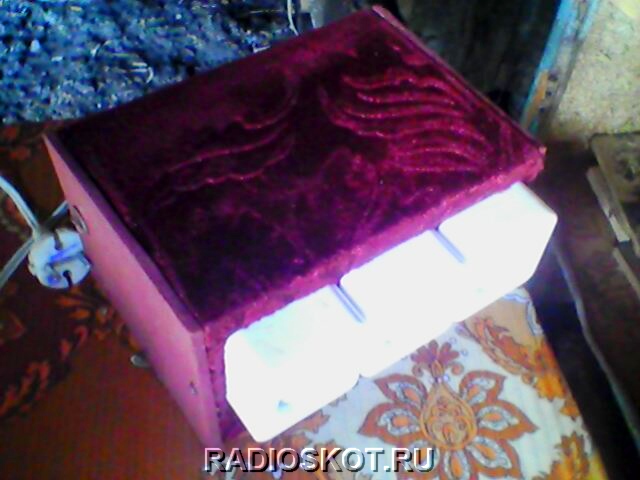
Assembled and checked. Works very well. Here is the device itself in the case:

This is the arrangement of elements inside the box that I chose. It is better to switch on via a diode bridge. It's cheap. But I think it’s not this that’s important to a radio amateur, but the repetition of the device itself. Even a beginner can solder the circuit. The finished color music device operates without interference, and does not strain the thyristors for a long time. They don't even heat up. Author of the material: Max.
This simplest light music has only one element. Yes, absolutely alone and nothing but: no resistors, no transistors... It is quite possible to assemble such a light and music installation in 30 minutes. All you need is one solid state relay.
Solid-state relays appeared on the market relatively recently and have already confidently conquered the radio electronics market. It’s understandable, I’ll give you the main advantages.
- - Performance.
- - Galvanic voltage isolation.
- - Quiet compared to a conventional relay.
- - Zero crossing detector.
A solid-state relay, in essence, apart from the name, has nothing in common with a mechanical relay, which everyone usually imagines when hearing this name for the first time. This is a regular triac switch, with control and decoupling circuits.
This miracle is quite inexpensive and can be easily bought on our favorite Aliexpress.com
There are many different versions of relays on the radio market: small and large, powerful and low-power. I took this:
Firstly, it has screw terminals for connection. Secondly, it can switch a load with a voltage of 24-380 V and a current of up to 60 A. Of course, I took it overkill for other purposes. To control a garland, it is enough to take from 2 A. Thirdly, the control voltage is from 3 to 32 volts, pulsed. Just what we need, since we will control the relay directly with the sound supplied from the output of the low-frequency amplifier.
Light and music circuit

A solid-state relay is connected to the open circuit of a lamp or garland. And the sound from the speaker is supplied to the input of the solid-state relay. The scheme couldn't be simpler. The main thing is not to confuse the conclusions. Now, as soon as the music starts playing in the speaker, the garland will immediately start blinking in time with the music.
We take the output from the amplifier from any channel, left or right. You can connect between the outputs so that the garland flashes with a stereo effect. If there is a subwoofer output, you can connect it to it. Or you can take two garlands and two relays and connect to different channels. There are a lot of options, choose any one you like.

I added a park of toggle switches to the circuit for switching. The first toggle switch in the diagram is so that you can simply turn on the garland in normal mode. And the second is to turn off the influence of music on her.
Thanks to galvanic isolation, high mains voltage is reliably isolated and will not pass through the speaker and amplifier.
I took a plastic container and placed sockets there to connect the load. I made holes for the toggle switches and connected the entire system.
How to make color music and please your friends? In modern radio engineering there is a huge variety of radio elements and LEDs. Using advances in electronics, radio amateurs can make a DMU with their own hands. A wide range of colors, bright and rich light, high speed of response of various elements, low energy consumption. This list of advantages can be continued endlessly.
The working principle of color music
LEDs assembled according to the circuit blink from an existing sound source (this can be a player or a radio and speakers) at a certain frequency. Benefits of using LEDs before those previously used in installations:
- luminous saturation of light;
- wide color range;
- good speed;
- low energy intensity.
The simplest color schemes
 Simple light music that can be assembled has one LED, powered by a DC source with a voltage of 6 - 12 V. You can assemble a circuit using an LED strip and selecting the necessary transistor. The disadvantage is that there is a dependence of the LED blinking frequency on the sound level. In other words, the full effect can be observed only at one sound level.
If you lower the volume, there will be a rare blinking, and if you increase the volume, a constant glow will remain. This drawback can be eliminated using a three-channel sound converter.
We work according to the simplest circuit using transistors using filters. In order to collect it, 9 volt power supply required, which will allow the LEDs in the channels to glow. To assemble three amplification stages you will need KT315 transistors (analogous to KT3102). Multi-colored LEDs are used as a load. A step-down transformer is used for amplification. Resistors perform the function of adjusting LED flashes. The circuit contains filters for passing frequencies. You can improve the circuit and add brightness; for this, 12 V incandescent light bulbs are used. Control thyristors will be needed. The entire device must be powered from a transformer. Using this simple scheme, you can already work with the filter.
Color music using thyristors, can be assembled even by a novice radio technician. The first thing you need to do is select an electrical circuit. For such an installation, a 12 volt power supply is required. It can work in two modes: as a lamp and as a color music. The mode is selected by a switch installed on the board.
When making light music for your home, you need to make a printed circuit board. To do this, you need to take foil fiberglass with dimensions of 50 x 90 mm and a thickness of 0.5 mm. The board manufacturing process consists of several stages:
- preparation of foil PCB;
- drilling holes for parts;
- drawing paths;
- etching.
The board is ready, components have been purchased. Now the most crucial moment begins - wiring of radio elements. The final result will depend on how carefully they are installed and sealed. We assemble our printed circuit board with components soldered on it into a lampshade that we have at home.
Radioelements for an electrical circuit are quite affordable; it will not be difficult to purchase them at your nearest electrical goods store.
Suitable for color and musical accompaniment wirewound resistors with a power of 0.25 - 0.125 W. The amount of resistance can always be determined by the colored stripes on the body, knowing the order in which they are applied. Trimmer resistors can be both domestic and imported. Capacitors are oxide and electrolytic. Some oxide capacitors may have a polarity that must be observed during installation. Diode bridges are available ready-made, but if there are none, then a rectifier bridge can be easily assembled using diodes of the KD or 1N4007 series. LEDs are ordinary ones with a multi-colored glow. The use of LED RGB strips is a promising direction in radio electronics.
Assembling color music for a car
 If you manage to please with color music from an LED strip with your own hands, then a similar installation with a built-in radio Can be assembled for car. It is easy to assemble and quick to set up. It is proposed to place the set-top box in a plastic case, which can be purchased in the electrical and radio engineering department. The installation is reliably protected from moisture and dust. It is easy to install behind the dashboard of your car. An excellent lighting effect is achieved if you use multi-colored (RGB) tape. The case can also be made independently using plexiglass.
Plates of the required dimensions are selected, two holes are made in the first of the parts (for power supply), and all parts are sanded. We assemble everything using a heat gun. The body is ready.
DIY color music, video:
Almost all color music devices of sufficient power are designed for the use of conventional incandescent lamps. There are also CMU circuits on LEDs on the Internet, but they are usually for low-power LEDs. How to connect 50-100 watt LEDs to such a device? You can take as a basis one very good color music scheme (also with sound control via a microphone) and slightly modify the output part - get the desired result.
CMU circuit for high-power LEDs
 Schematic diagram of the CMU for 220V
  Schematic diagram of the CMU for 12V


The electrical power supply for the input part of the frequency processing is made on a piece of a universal board. The transformer was taken from some kind of radio. It is ideal because it is symmetrical and has 10V windings. BT151/600 thyristors were used as powerful switches, with a margin so that they would not burn out from high currents.


The circuit can be made completely isolated from the network if the executive part is used using triacs and optocouplers.


When testing, temporarily install resistors of rated resistance and power from 10 W instead of LEDs.
CMU with 12 V LED strips
If you want to use 12 V DC LED strips in the CMU, then you can power the entire circuit with the same 12 volts from a pulse network driver, and assemble the output part using high-power field-effect transistors.

A version of the diagram is shown above. Here resistor R2 sets the current limiting of the LED strip (or a powerful single LED).
By the way, when installing individual high-power LEDs, for example 100 watts (32 V at 3 A), supply the supply voltage from the driver through the LED to the drain of the field-effect transistor (after making sure from the datasheet that it can withstand such U/I parameters), and the specified Use the resistor above to set the desired current level.


The body is made of wood (easier to find the material and easier to process). The holes for the lamps are drilled with large cutters. Naturally, on the front there are all the necessary knobs for adjusting signal levels and HF-MF-LF channels and a power button.