Absolute pressure in the suction pipe of the pump. Great encyclopedia of oil and gas
The operation of pumps consists of two processes: suction and discharge. Any type of pump is characterized the following parameters: suction height, discharge height, total head, flow, power and total efficiency (efficiency).
Suction lift.
There are theoretical, vacuum and geometric (practical) suction heights.
The rise of water in the suction pipe of the pump occurs under the influence of the difference between atmospheric pressure and pressure (vacuum) in the pump itself. Therefore, the theoretical suction height of the pump (Nt) is equal to 1 atmosphere and is 10.33 meters of water column, or 760 mm. mercury column, or 1 kgf/cm 2, or 10 5 Pa is practically unattainable. By improving the design and materials of the pump, its suction height can be brought closer to the Nt value.
Vacuum suction height (N in) is the amount of vacuum created by the pump, and in an energetic sense it is the energy, expressed in meters, that is necessary for the liquid to rise to the suction height. Hv depends, as a rule, on the power of the pump that creates the vacuum and is measured in meters of water column. The readings of the vacuum gauge installed on the pump correspond to the vacuum suction height. For a fire pump of the PN-40 series and its analogues, N in = 8 m of water. Art.
The geometric (practical) suction height H g is the difference in elevation between the surface of the water and the axis of the pump. The geometric suction lift depends on the values and magnitudes of several parameters:
The value of Hg is directly influenced by atmospheric pressure, which varies noticeably depending on the altitude above sea level. For example, at an altitude of 0 m above sea level, the atmospheric pressure is 10.33 m of water. Art., and at an altitude above sea level of 2000 m - 7.95 m of water. Art.
N g strongly depends on the saturated vapor pressure of the sucked liquid. Saturated vapor pressure is the pressure at which a liquid boils at a given temperature (we are talking about liquid pressure below atmospheric). The vapor pressure and therefore the suction lift are highly dependent on the temperature and type of liquid being pumped. It is known that as pressure decreases, the boiling point of a liquid decreases. If the suction pressure (it is naturally lower than atmospheric pressure) P sun is lower than the saturated vapor pressure of the sucked liquid P n , then steam formation will begin and the pump will fail.
Thus, a prerequisite for normal pump operation is:
P n< Р вс < Р атм
For example, at a water temperature of 100 ºС Р n = Р atm = 1 kg/cm 2 (10 m. water column), and at a water temperature of 20 ºС Р n = 0.024 kg/cm 2 (0.24 m. water column). Art.), therefore, the higher the temperature of the liquid, the more difficult it is to pick it up with a pump. Associated with this phenomenon cavitation– the process of formation of air bubbles in a liquid. During cavitation, self-boiling of the liquid occurs, vapor bubbles are carried away by the moving flow and, encountering the solid surfaces of the housing and impeller, are destroyed (“collapsed”). In this case, a lot of energy is released, which damages and even with prolonged exposure destroys the surfaces of the internal cavity of the pump (the phenomenon of cavitation erosion). Cavitation is accompanied by noise and crackling inside the pump. To avoid premature wear of the working parts of the pump, its operation in cavitation mode is not allowed.
Cavitation phenomena can occur when the pump operates with a large geometric suction height. Therefore, the suction height must be such that cavitation cannot occur.
The maximum permissible suction lift can be determined by the formula:
where: Р n – saturated vapor pressure;
γ – specific gravity liquids;
h sun – pressure loss in the suction pipeline;
ΔН – cavitation reserve.
The cavitation reserve value is set so that there is no significant reduction in pressure and the rate of cavitation erosion is limited. For example, for pumps of the PN-40 series, the cavitation reserve is 3 m.
Cavitation phenomena can also occur at high pump flows, due to a decrease in pressure (increase in vacuum) in the pump inlet. Therefore, when cavitation occurs, it is necessary to reduce the pump flow.
Finally, the geometric suction lift depends on the head loss in the suction line or the amount of resistance overcome in the suction line.
h sun = S Q 2 ,
where: S – resistance of the suction line;
Q – pump flow.
From all that has been said, it follows that the geometric (practical) suction height H g is determined by the expression:
N g = N in – h sun – h rp – h r.atm,
where: Нв – vacuum suction height;
h sun – pressure loss in the suction line;
h рп – temperature pressure loss (saturated vapor pressure);
h r.atm – pressure loss, depending on the altitude of the area above sea level.
For example, for a fire pump of the PN-40 series, N g practically does not exceed 7 m when operating under normal conditions, i.e. at atmospheric pressure P atm = 1 kg/cm 2 (10.33 m. water column) and water temperature 20 ° C.
Typically, the permissible suction height is indicated by pump manufacturers in product data sheets.
Discharge height.
There are geometric and manometric discharge heights.
Geometric discharge height is the vertical distance in meters from the pump axis to highest point injection N n.
The manometric discharge height is the pressure created by the pump N mang. The manometric discharge height (pressure gauge reading) is always greater than the geometric discharge height (the actual liquid supply point) due to the resulting losses in the pressure line.
N man = N n + h n,
where: h n – pressure loss in the pressure line, h n = S·Q 2 ;
S – pressure line resistance;
Q – pump flow.
There are no theoretical limits for the discharge height, but in practice it is limited by the strength of individual parts of pumps and pipelines, as well as the power of the pump drive motors.
Full pressure.
The total pressure developed by the pump H is spent on lifting the liquid, overcoming the resistance in the suction and pressure pipelines and creating free pressure.
N = N g + h sun + h n + N st
where: N g – geometric height of water rise (m);
h sun + h n – pressure loss in the suction and pressure lines (m);
N sv – free pressure (m).
In practice, the total pressure developed by the pump is estimated from the readings of the pressure gauge and vacuum gauge.
Pump supply.
Pump flow is the amount of liquid pumped by the pump per unit time. A distinction is made between mass flow (kg/s) and volumetric flow (m 3 /min or l/s). Most often, the flow of fire pumps is indicated in volumetric units: m 3 / min or l / s.
There is a relationship between the amount of fluid entering pump Q 1 and the amount of fluid leaving pump Q 2:
Q 1 = Q 2 + Q y,
where: Q y – volumetric fluid leakage through gap seals.
Pump power.
During operation, the working parts of the pump supply energy to the fluid flow. This energy is supplied from the engine.
To correctly assess the energy performance of a motor-pumping unit, it is necessary to distinguish between useful (effective) and consumed power.
The useful (effective) power (Ne) of the pump is used to perform work to move a certain volume of liquid Q to a height H and is determined by the formula.
| |
Where: ρ – liquid density, kg/m3;
g – free fall acceleration, m/s 2 ;
Q – pump flow, m 3 /s;
N – pump head, m.
The power consumed by the pump is always greater than the useful power, because part of the energy is spent on mechanical, hydraulic and volumetric losses in the pump. Power consumption is the power N supplied to the working parts of the pump. It is determined by the formula:
where: M – torque on the pump (motor) shaft, N m;
ω – angular speed of shaft rotation, s -1.
Full pump efficiency.
When energy is transferred from the pump to the pumped liquid, volumetric, hydraulic and mechanical energy losses occur
Volumetric efficiency.
It is known that the actual pump flow is always less than the theoretical flow, i.e. The amount of liquid leaving the pump is always less than the amount of liquid entering the pump. This happens due to:
§ leakage of liquid through seals, valves and pistons, and the degree of leakage depends on the accuracy of manufacture and condition of these pump parts;
§ delayed opening and closing of valves;
§ presence of air in the liquid.
The volumetric efficiency value characterizes the degree of tightness of the pump and is determined by the formula:
where: N – actual (developed) pump pressure;
ΔН – pressure loss to overcome the resistance inside the pump;
Н + ΔН – theoretical pump pressure.
Mechanical efficiency.
Mechanical efficiency is the power loss due to friction in bearings, shaft seals, etc. The value of mechanical efficiency characterizes the quality of manufacture and rational design of bearings, oil seals (cuffs) and other components where friction of parts occurs.
Mechanical efficiency is determined by the formula:
Technical requirements for pumping units of fire trucks
Due to the peculiarities of operation, the following basic requirements are imposed on the pumping units of fire trucks:
§ small overall dimensions and weight, which is necessary for the rational use of the carrying capacity and volume of the fire truck body;
§ high reliability, including when working on contaminated water;
§ constant readiness to work;
§ high cavitation properties;
§ flat shape of the pressure characteristic, i.e. a slight change in pump pressure in the flow range from zero to maximum at a constant speed (with a steeply falling shape of the pressure characteristic, a decrease in flow entails a rapid increase in pressure, which can cause rupture of the pressure hoses, and an increase in flow – significant reduction in pressure);
§ consistency of pump and engine parameters, in the absence of which the pump parameters cannot be implemented on a fire truck;
§ minimum time filling the suction pipeline and pump with water before starting using a vacuum system (no more than 40 seconds from a geometric suction height of at least 7.5 m);
§ simplicity and ease of control of the pumping unit;
§ the possibility of long-term continuous operation at maximum mode in a specified range of ambient temperatures (the design of normal pressure pumps must ensure them continuous work in nominal mode for at least 6 hours, pumps high pressure– at least 2 hours);
§ free access for Maintenance, its simplicity and convenience (the absence of elements that require periodic adjustment, a minimum number of lubrication and water drainage points, the possibility of partial disassembly of units directly on the fire truck);
§ low noise level and absence of vibrations during operation (the average sound level created by the pump when operating in nominal mode should be no more than 85 dB);
§ use of the same types of oils and lubricants that are used for the units and components of the fire truck chassis.
Fire trucks are usually equipped with centrifugal pumps. This is due to the fact that centrifugal pumps have a number of important advantages: uniform supply of fire extinguishing agents (supply without pulsations); the ability to work “on its own” (i.e., when the fire nozzle is blocked, the fire hose is clogged or broken, the pressure in the water supply system does not increase excessively), ease of control of the pump and its maintenance when operating in fires.
For fire trucks, it is important that centrifugal pumps do not require a complex engine drive, and their dimensions and weights are relatively small.
At the same time, centrifugal pumps also have a number of disadvantages, the most important of which is that they are not self-priming - they work only after the suction line and pump are first filled with water. This disadvantage is compensated for by devices that allow the suction tracts and pump cavity to be filled from tanks. In addition, auxiliary pumps are installed on fire trucks to fill the cavity of the suction hose and the pump housing with water. For this purpose, gas-jet, rotary, piston and other pumps are used. Auxiliary pumps operate briefly, only when the centrifugal pump is turned on. The installation of such pumps complicates the design of the pumping unit and requires an additional drive for their operation.
Pressure and energy characteristics of a centrifugal pump determines the dependence of pressure, power consumption and efficiency. from pump supply. These dependencies are depicted graphically by curves Q–H, Q–N and Q-η at a constant speed of rotation of the pump impeller n (see Fig. 3.7).
The pressure and energy characteristics are constructed as follows. By adjusting the degree of opening of the valve on the discharge pipe, at a constant speed of rotation of the pump shaft, different flow values Q are obtained. Each value of Q corresponds to pressure H, power N and efficiency. η pump. Then the feed values are plotted on the abscissa axis on the accepted scale, and the obtained values of H, N and η are plotted on the ordinate axis. The resulting points are connected by smooth lines. From the graph of the Q-η characteristic (see Fig. 3.7) it can be seen that
 |
maximum efficiency value (point A) corresponds to a certain flow Q A and pressure N A. Point A is called optimal and corresponds to the optimal operating mode of the pump.
The influence of the impeller rotation speed on the operating parameters of a centrifugal pump is manifested as follows.
The flow of a centrifugal pump varies in proportion to the speed of rotation of the impeller: Q 1 /Q 2 = n 1 /n 2.
The pressure developed by the pump varies proportionally to the square of the impeller rotation speed: N 1 / N 2 = (n 1 / n 2) 2.
The power consumed by the pump varies proportionally to the cube of the impeller rotation speed: N 1 / N 2 = (n 1 / n 2) 3.
1. Task
Determine the suction lift of a centrifugal pump if some pump characteristics are known. Brand TsV-1.1, pump motor power consumption N=2.5 kW, speed n=2900 rpm. Suction pipe diameter d 1=50mm, length l=10m, water temperature 40 o C. 1 - pressure pipeline; 3 - centrifugal pump; 4 - suction pipeline; 5 - well filled with liquid medium; Figure 1 - Centrifugal pump installation diagram Calculation of suction height of a centrifugal pump Suction height is the distance from the liquid level in the well to the pump axis. To obtain the equation for determining the suction height, we will compose the Bernoulli equation (see formula 1) for the section passing along the surface of the well and the section passing through the suction pipe of the pump (see Fig. 1). After some transformation for the given conditions of the Bernoulli equation, we can obtain formula 2 to determine the suction height. where Rat is atmospheric pressure, mm.in.st.; Рп - water vapor pressure according to table 1, at a given temperature equal to Рп=0.75 mm.in.d.; r - density of the pumped liquid - water r=1000 kg/m3; - free fall acceleration g=9.81 m/s. φ - safety factor lies in the range from 1.1 - 1.4, 1.1 is accepted; N is the total pressure created by the pump, m (see Fig. 2). δ - cavitation coefficient, determined by formula 3; ws - losses in the suction pipeline, calculated according to formula 5. Table 1 - Water vapor pressure at t, oC t, o C510203040506070100R P 0,090,120,240,430,751,252,03,1710,33
where sk is a coefficient that takes into account the cavitation characteristics of the pump, in the range from 500 to 1000, 1000 is taken; s is the speed coefficient, determined by formula 4. where n is the number of revolutions of the pump motor, rpm; is the pump flow rate, m3/h (see Fig. 2); The parameters, pump flow Q and pressure H, are determined according to Figure 2, according to the brand and power of the pump. Figure 2 - Summary graph of H-Q fields where l is the length of the suction pipeline, m; ζ - coefficient of local resistance, take the value 10; λ - pressure loss coefficient along the length of the pipeline, determined by formula 6; - diameter of the suction pipeline, m; υ - suction speed, in our case it will be different for each of the points, while all values will be less than 1, so we take the value 1, m/s; centrifugal pump suction height where Re is the Reynolds number, formula 7. where ν is the coefficient of kinematic viscosity, m2/s. Based on these conditions, we accept 1.01∙10-6 m2/s. Solution of the calculation task We determine the values of H, Q using the summary graph. A minimum of 5 values necessary for further calculations are selected, the accepted values are entered into Table 2. Table 2 - Accepted numerical values of H-Q Parameter Point number 12345H, m5055657085Q, m 3/h6.5654.52.8 We find losses in the suction pipeline according to formula 5. We calculate the unknown factors of this formula: After carrying out minor transformations, we get Reynolds number: We find the losses in the suction pipeline using the transformed formula 8: We calculate the speed coefficient ns for the first point H-Q values, according to formula 4. We determine the coefficient ck, taking into account the cavitation characteristics of the pump: We find the suction height of the pump for the first point, according to formula 2. For the conditions of this problem, the denominator can be neglected, as a result of the transformation, we obtain the following formula: Let's substitute the values found above and calculate the suction height using the last formula: The calculation of points 3.3 and 3.5 is performed for all five H-Q points, upon completion of the calculations, the results obtained must be entered into Table 3. Table 3 - Calculation results As a result of the calculation, the goals of the assigned task were achieved. Thus, knowing some characteristics of a centrifugal pump, it is possible to determine its parameters, one of which is the suction height, which is proven by calculation. The obtained values are summarized in a table, which allows you to more clearly see the dependence of the parameter values on each other. Bibliography 1 "unienc". Products.// Unienc [Electronic resource]; [site]/Pumps. - Electronic text data. - Moscow, 2014. - Access mode: http://unienc.ru/296/10240-centrobezhnyy-nasos.html. 2 Cherkassky, V. M. Pumps, fans, compressors. Textbook for thermal power engineering specialties of universities. - / V. M. Cherkassky. - M.: Energoatomizdat, 1984. - 416 p. Polyakov, V.V. Pumps and fans. Textbook for universities. - / V.V. Polyakov, L. S. Skvortsov. - M.: Stroyizdat, 1990. - 336 p.
The pump operator realizes early on that he can easily move large quantities of fluid by running an industrial pump. The operator does not control the pump, it is controlled by the system. In particular, the pump is controlled by resistance in the pipes and fittings. This is the exact opposite of what most operators are trained to do.
When using a variable speed pump, the operator controls the flow and pressure through the pipelines in accordance with the volume requirements of the product sold. It's natural to think that operating a pump is similar to driving a car. Press the gas pedal and the car will go faster. Turn on your headlights and you're good to go at night. Press the brake pedal and stop.
But this is a wrong opinion. And everything works completely wrong. And this is the exact opposite of what most operators are trained to do.
Problems with pumps began to be resolved when it was understood that the system was dominant, and the pump was a controlled mechanism.
The system controls the pump. The system consists of an intake tank and a discharge tank, as well as all piping, elbows, valves, filters, process equipment and instruments. The system does not respond to the pump, it is the pump that responds to changes in the system.
If a pump is forced to do something it cannot do, it will fail frequently and prematurely. We call it mysterious pump failure, reactive maintenance, or unplanned downtime. So how do you know how the pump behaves inside the system?
The answer is simple, but not always realistic. The pump performance curve must be accessible and understandable to everyone involved with the pump, which is rarely the case.
Pressure gauges must be installed on both the suction and discharge pipes. This is another rarity. But all is not lost if such information is not available.
You can get some useful information from the pump and motor identification plate. The motor plate shows the rotation speed. The pump plate usually indicates the diameter of the impeller in millimeters. Knowing the rotation speed and diameter of the impeller, you can use the following table:
SOH- Shut-off head - shutdown pressure
BEH- Best efficiency head - pressure at the point of best efficiency
The first unwritten law:
At 1500 rpm, the diameter of the impeller in mm will give a reliable pump shutdown pressure in meters. The pump cut-out pressure is the start of the pump curve. It represents the maximum head at zero flow. As the impeller diameter and rpm change, the cut-out pressure will also change.
The second unwritten law:
Coordinates of pressure and supply at a point best efficiency pump (called the best efficiency point, BEP) are about 85% of the shut-off head.
The third unwritten law:
The pump should be operated at or close to its best efficiency point. See the table above. Consider a 225 mm wheel spinning at 1500 rpm. The cut-out head on most standard pumps will be very close to 17 meters. According to this, the pump flow should be about 14 meters.
To put it another way, if your piping system requires a head of 14 meters and you are using a 4-pole motor with a 50Hz supply current, then the pump should have an impeller of about 225 mm.
Unwritten laws are not written in stone. As with all laws, there are exceptions, depending on the design of the pump and the overall efficiency, the efficiency of the impeller (blade pitch, number of blades, and surface treatment), the conditions for the formation and presence of wear bands, the actual speed of the engine and some properties of the fluid. However, unwritten laws govern most industrial pumps. (The largest family of centrifugal pumps is the radial impeller water pump with an apparent speed of about 500-1500 units. This family covers about 85% of all centrifugal pumps.
If the pump speed or impeller diameter changes, the pump characteristics will change according to the laws of similarity.
The graph shows the important elements of a conventional centrifugal pump curve plotted on a head-flow graph. The vertical axis shows the pressure difference or height in meters, starting from zero. The horizontal axis contains the flow data in m3/h, starting from zero. 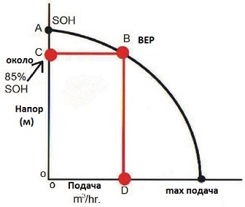
Figure 1. Important elements of a conventional pump curve
Point A- shutdown pressure
Point B- point of best efficiency on the curve
Point C- Pressure at the point of best efficiency (approx. 85% of cut-off pressure)
Point D- feeding at the point of best efficiency
Shutdown pressure is a simple concept. If you were to pump liquid into a vertical pipe that stretched into the sky, the pump would push the liquid into the pipe to a certain point beyond which it could not lift the column of liquid. The weight of the liquid (gravity) will be equal to the energy applied to the liquid. The supply stops because all the pump/motor energy is used to maintain altitude. This is the shutdown pressure.
On the curve there is a point called (BEP), the point of best efficiency, the coordinates of which are point C, which is the best head in meters, and point D, which is the best flow in m3/h.
Let's say you need a centrifugal pump to fill a tank from a source with a flow of 400 m3/hour. The pressure pipe rises above the top of the tank and falls down. The suction and the reservoir into which the water enters are under atmospheric pressure. The drop height is 21 meters. above the level of the power source. When pumping at a flow rate of 400 m3/h, the piping system consumes more than 5 meters of energy as friction and dynamic losses. These losses occur when passing through pipes, elbows, valves, technological devices and instruments. How would you specify a pump for such a system?
The pump must provide an effective head height of 26 meters (21 meters - height difference + 5 meters - resistance losses) at a supply of 400 m3/h. The impeller diameter for your pump should be around 300mm if it is paired with a 4-pole motor.
You will see this in the table. The shutdown pressure will be approximately 30.5 meters. The best efficiency point for this pump will be around 26 meters (85%), delivering 400 m3/h.
How do you know if the pump is performing as it should? Here it is important to use sensors and convert pressure into pressure. Incoming water at 26 meters would show a difference of 260 kPa on the pump pressure gauges.
If the suction pressure gauge shows 40 kPa, then at the discharge pipe it should show 300 kPa (pressure difference 260 kPa). If we have 120 kPa at the suction, then the pressure gauge should read 380 kPa (pressure difference 260 kPa.). A simple clip-on flow meter at this pressure will give a reading of 400 m3/h. Since the pressure difference in the pump is far from 260 kPa, it can be assumed that the number of maintenance and incomprehensible failures will increase on it.
It's really simple. Too many people try to make pumps complicated. This is not rocket science. It is clearly seen that you do not need to make abstruse decisions to solve the problem of a pump that has a pressure gauge only on the discharge pipe, while not having one on the suction to show the pressure difference. Many smart and educated people do this wrong.
It can be seen how technological devices contribute to the reliability of the pump. Pumps need operating sensors, or transducers, that indicate the pressure difference. Mechanics and equipment operators require training to interpret sensor readings. The pump is loaded when the differential pressure gauge readings rise or fall as predicted. This means that the bearings will soon suffer, or the seal will fail.
LECTURE No. 5
Centrifugal pumps
Plan
5.1 Basic definitions used in pump theory
5.2 Diagram and principle of operation of a centrifugal pump
5.3 Combined operation of pumps and network
5.4 Cavitation in pumps and permissible suction lift
5.1 Basic definitions used in pump theory
Pump theory uses a number of terms and definitions that apply to all types of pumps. Let's consider the operation diagram of a pump included in a system that supplies water from a water supply source to a pressure tank (Figure 2.9). When the pump operates, a vacuum is created in the suction chamber, which ensures that water rises through the suction pipe from the water intake well into the pump. This vacuum must be sufficient to lift water from the well to a height h wec (from the water level in the well to the center of the pump), to overcome energy losses in the suction line h wec , and also to create velocity in the suction pipe. Vertical distance from the water level in the well to the center of the pump h ec called geodetic suction height; energy loss in the suction line h wec called suction losses.
The liquid entering the pump is given energy (mainly in the form of pressure energy), which is spent on overcoming the resistance in the pressure pipe through which the liquid moves, and on lifting the liquid into the reservoir.
Figure 2.9. Pump stability diagram
The vertical distance h in from the center of the pump to the water level in the tank is called the geodetic injection height; energy losses in the pressure line are called injection losses h wн.
Sum of three quantities
N man + N vac + ∆h = N m, (5.1)
namely: the readings of the pressure gauge and vacuum gauge, expressed in meters of water column, and the vertical distance between the points of connection of the instruments, is called the gauge pressure of the pump.
The total pump pressure can be expressed as follows:
The technical (mode) parameters of the pump are:
flow (performance) Q - amount of liquid pumped per unit time, m 3 /s;
pressure N - the difference in the specific energies of the fluid flow at the outlet of the pump and at the inlet, i.e. weight increment of the specific mechanical energy of the fluid flow passing through the hydraulic machine (the weight increment of energy has the dimension of meters of water column and characterizes the vertical height of the rise of the fluid using a pump);
useful power N - power imparted by the pump to the flow of liquid passing through it, kW;
expended (consumed) power N e - power on the shaft of the electric motor (pump drive), kW;
efficiency factor η - ratio of useful power to engine power consumption, %:
5.2 Diagram and principle of operation of a centrifugal pump
Let's consider the diagram of a single-wheel pump with a horizontal shaft (Figure 2.10)
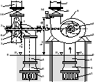
Figure 2.10. Main elements of a pumping unit
The main and most important part of a centrifugal pump is the impeller 1, connected to the working shaft 2. The impeller, consisting of curved blades mounted in disks, is enclosed in a stationary spiral chamber 3. The liquid is supplied to the pump through a suction pipe 4, which at its end has a mesh that prevents the pump from sucking in objects floating in the liquid, and check valve 6, necessary for priming the pump before starting. Through the discharge pipe 7, the liquid from the pump enters the pressure pipeline. On the same shaft as the impeller there is a motor that drives it.
At the intersection of the working shaft and the casing, oil seals 8 with a sealing packing are installed to prevent water leakage and air from entering the suction pipe.
The pumps are equipped with a vacuum gauge B, a pressure gauge M, a valve for filling the pump 9 (sometimes), as well as a valve 10 on the discharge pipe, which serves to regulate the flow and disconnect the discharge line from the pump. In addition, a check valve is usually installed in the discharge pipe, which automatically closes when the pump stops, disconnecting the latter from the pressure line. The check valve in the suction pipe is closed.
After the entire pump and suction pipe are filled with liquid, the motor is turned on, which rotates the impeller. Liquid particles move under the influence of centrifugal force from the entrance to the pump to the exit from it. As a result of this movement of liquid towards the discharge line in the suction pipe, a vacuum is created. Then the external (atmospheric) pressure acting on the free surface of the liquid will open the lower valve 6 and the liquid from the well will begin to flow into the pump. This creates a continuous flow of liquid through the centrifugal pump.
When fluid moves through the impeller, the mechanical energy of the engine is converted into the energy of the moving fluid.
5.3 Combined operation of pumps and network
The operation of the pump and pipeline is related to the following two dependencies
where N is the pump pressure; Q – water supply by pump; h w – hydraulic resistance of communications pumping station, water pipelines and networks;
In the practice of designing and analyzing operating modes of pumps, the method of graphic-analytical calculation of the joint operation of the “pumps - network” system is widely used.
Required pressure to supply water to the consumer
Н = Н st + h w , sun + h w , n + h w , tr, (5.3)
where h w, sun – pressure loss in the suction line; h w , H – pressure loss in the discharge line from the pump to the point of connection of the water pipelines; h w , mp – pressure losses in the network water pipelines.
Losses hw,n and hw,tp, as a rule, are combined, i.e. h n = h w,t p + h w,n.
The pumps in the system operate in accordance with their characteristic relationship between Q and H, i.e. The pump operating schedule is determined by its operating characteristic Q – H. To construct the graphical characteristic Q – H tr of the water supply and distribution system, we will use the well-known hydraulic equations.
Calculation of pipeline network characteristics
Calculation of pressure losses in local resistances and along the length of the pipeline is carried out for the pump most distant.
The total pressure loss in the pipeline is determined by the formula:
where λ in and λ n are the friction resistance coefficients of the suction and discharge pipelines, respectively:
![]() ,
(5.5)
,
(5.5)
l V , l n– respectively, the lengths of the suction pipeline from the intake filter (mesh) to the pump and the discharge pipeline from the pump to the point of water outflow on the surface, determined according to the adopted drainage scheme, m;
Sums of local loss coefficients of suction and discharge pipelines. In this case, it is necessary to ensure that the following conditions are met: .
l– pipeline length; d in, d n – respectively, the calculated internal diameter of the suction and discharge pipelines; υ nsr – average speed of water movement in pipelines.
The speed of water movement is taken depending on the diameter of the pipeline according to table 2.1.
When constructing the characteristics of an external network, it is convenient to use the formula:
H c = H r + R c R 2,
or, taking R c = H p /Q 2 we get
H c = H r + R c Q 2 , (5.6)
where H r is geodetic height, Q is feed, m 3 /s.
Using the graphic-analytical method, we combine the pressure characteristic of the pump H=ƒ(R) and the network characteristic H c =H r +R with Q 2 on the same scale. The intersection point will determine the actual mode of a given pumping unit for a given network.
5.4 Cavitation in pumps and permissible suction lift
One of the main conditions for the normal operation of hydraulic systems is the absence of cavitation. To do this, it is necessary that the pressure at any point in the liquid flow be greater than the saturated vapor pressure.
The liquid moves in the suction path of the pump under the influence of pressure on the free surface of the air intake. The magnitude of this pressure is always limited and is most often equal to atmospheric pressure.
In conventional designs of centrifugal pumps, the lowest pressure is observed near the entrance to the cylindrical section of the impeller on the concave side of the blades, i.e. where the relative speed ω and the corresponding kinetic energy ω 2 /2, J/kg, reach their highest values, Figure 2.11, zone A. If in zone A the pressure is equal to or less than the saturated vapor pressure corresponding to the temperature of the suction liquid, then the phenomenon occurs , called cavitation.
The physical picture of cavitation consists of the boiling of a liquid in a zone of low pressure and the subsequent condensation of steam bubbles when boiling water is carried into a region of high pressure. In this case, the cavitation process is distributed along a certain length of the flow. Cavitation can be a local process in cases where the pressure in the section pulsates around an average value equal to the saturated vapor pressure at the temperature of the suction liquid. In this case, the processes of boiling and condensation of steam bubbles occur with high frequency, in a pulsating manner.
Figure 2.11. To determine the minimum pressure in the impeller
In any case, cavitation during the rapid condensation of a vapor bubble, the liquid surrounding it rushes to the center of the bubble (condensation center) and at the moment its volume closes, due to the low compressibility of the liquid, it produces a sharp point blow. According to modern data, the pressure at the points of closure of steam bubbles during their condensation in cavitation processes reaches several megapascals.
If a bubble of steam at the moment of its condensation is on a surface limiting the flow, for example on a working blade, then the impact falls on this surface and causes local destruction of metal, called pitting. Modern research shows that cavitation is accompanied by thermal and electrochemical processes that significantly affect the destruction of the surfaces of the flow cavity of pumps.
The nature of pitting depends on the material from which the pump flow part is made. Thus, pitting cast iron parts, for example, the working blades of low-pressure pumps, produces a spongy structure with a very uneven surface and tortuous narrow cracks that penetrate deep into the metal and compromise the strength of the part. In high-pressure pumps operating at high rotation speeds, with parts made of ordinary structural and alloy steels, pitting appears in the form of smooth, as if machined, depressions and grooves. There are no materials that are absolutely resistant to cavitation. Heterogeneous brittle materials such as cast iron and ceramics resist cavitation very poorly. Of the metals used in pump construction, the most cavitation-resistant are alloy steels containing nickel and chromium.
Cavitation is harmful not only because it destroys metal, but also because a machine operating in cavitation mode significantly reduces efficiency.
Pump operation in cavitation mode is externally manifested by noise, internal crackling, increased vibration levels, and in case of highly developed cavitation - shocks in the flow cavity, which are dangerous for the pump.
It is customary to divide the cavitation process into three stages. In the initial stage, the cavitation zone is filled with a mixture of liquid and more or less large vapor bubbles. In the second stage, large cavities are formed in the cavitating flow on the limiting surface, which are torn off by the flow and form again. This is the stage of developed cavitation. The third stage is supercavitation: the entire streamlined element of the hydraulic machine lies in the cavity area.
Pump operation in the initial cavitation stage is undesirable, but is acceptable if the pump parts are made of cavitation-resistant materials. In the stages of developed cavitation and supercavitation, the operation of the pump becomes unreliable and therefore unacceptable.
As stated earlier, cavitation usually occurs in the suction path of the pump on the blades of the impeller, however, cavitation processes can also occur in pressure flows in places where liquid is removed from the working blades, guide vanes, and control elements. Measures to prevent the occurrence of cavitation in pumps: limiting the fluid speed in the flow cavity of pumps, using rational shapes of cross-sections of the flow cavity and blade profiles, operating pumps in modes close to design ones.
In multistage pumps, the impeller first along the fluid path is most susceptible to cavitation, because the pressure at its inlet is the lowest. To increase the cavitation qualities of such pumps, an upstream axial wheel or auger consisting of two or three turns is installed in front of the first stage. They are made from cavitation-resistant materials and develop pressure at the inlet of the first wheel of a multistage pump that prevents the occurrence of cavitation.
When choosing the operating mode of a pumping unit, it is necessary to focus on the physical properties of water (Table 2.2), the dependence of the suction height H in m.w.c. on water temperature (Table 2.3) and the dependence of n s on the cavitation speed coefficient C (Table 2.4).
Table 2.2 - Physical characteristics of water
Table 2.3 - Dependence of water suction height on its temperature
Table 2.4 - Dependence of n s on C
The main task when operating pumps is to prevent the possibility of cavitation occurring in the pump. This is achieved by correct selection of the geometric suction height of the pump N g.vs, that is, the height to which the pump is raised above the liquid level

Figure 2.12. Calculation diagram for determining the permissible geometric suction height of the pump
In accordance with the calculation scheme shown in Figure 2.12, we assume that the water in the tank or pond is at temperature t and atmospheric pressure P atm. Let us write the condition for the onset of boiling in relation to the problem under consideration, expressing pressures in the form of pressure heads.
P np /ρg = P atm /ρg – N g.sun – h g.sun - h kp - d sun /2, (5.7)
where h sun is the pressure loss in the suction line of pipelines up to the pump; h kp - critical cavitation reserve, i.e. the minimum permissible excess of pressure in front of the pump over the pressure of saturated water vapor; ρ is the density of the transported medium (water) at the design temperature; d sun is the inlet diameter of the impeller, usually approximately equal to the diameter of the suction pipe of the pump.
The critical cavitation reserve h cr of a pump depends on the design of the pump and its operating mode. It is calculated using the formula:
where n is the rotation speed of the impeller, rpm; Q - pump flow, m 3 /s; C - coefficient of cavitation speed, is a similarity criterion and depends on the design of the pump. For ordinary pumps it is 600-800, for special condensate pumps - up to 3000.
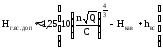
Considering that it is necessary to guarantee the impossibility of cavitation occurring, the critical cavitation reserve h kp is taken in calculations with a correction factor of 1.15 ÷ 1.2. Losses on the suction line can be calculated as for any pipeline using the well-known formula h = (λl/d + ∑ ζ. sun)pw 2 /2g Taking this into account and using (23) and (24), we obtain the final expression for calculating the permissible geometric suction height :
![]() .
(5.9)
.
(5.9)
The anti-cavitation head reserve should be taken equal to about 25% H g.vs.kr, and therefore in the case under consideration
 .
(5.10)
.
(5.10)
When calculating the permissible suction height of double-suction pumps (type D), half of the pump’s full flow should be substituted under the root sign in formula (5.10).
It should be borne in mind that the pump shaft speed has a significant influence on the permissible suction lift.
The cavitation energy reserve at the level of the suction liquid gH kav depends on the saturated vapor pressure at the temperature of the suction liquid. Therefore, from (5.10) it follows that Hg.all.add depends on the temperature of the liquid. From formula (5.10) it is clear that when the level of the suction liquid is located above the axis of the pump, the increase in temperature increases the permissible geometric suction height. If the level of the sucked liquid is located below the axis of the pump and the pressure on the surface is atmospheric, then the higher the temperature of the liquid, the less N g.all.add. Obviously, at a certain temperature that determines a sufficiently high value of p zn.p, the value of H g.vs.add becomes equal to zero and a further increase in temperature will require installing the pump below the level of the sucked liquid.
In practice, two different cases of positioning the pump relative to the receiving tank are possible.
The installation shown in Figure 2.13a is typical for pumps supplying liquids with low temperatures, and the installation in Figure 2.13b is for pumps supplying liquids at high temperatures, as well as when pumps suck cold water from containers with a sufficiently high vacuum.
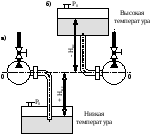
Figure 2.13. Two cases of installing the pump relative to the level of the suction liquid.
Installations made according to the diagram in Figure 2.13a, b are often found in thermal power engineering in regenerative heating and power supply schemes for steam boilers.
When the pump supplies hot water, the container from which it draws must be located above the pump (for example, in the case of a booster pump drawing feed water from a deaerator). For reasons of convenience of construction work and installation, it is advisable, if possible, to reduce the installation height of the receiving container required by the calculation. This can be achieved by increasing the diameter of the suction pipeline, reducing its length, as well as choosing a rational design of those elements of the suction tract that reduce local pressure losses.
In some cases, the permissible suction height can be changed by decreasing or increasing the pressure in the container from which suction occurs.
If the level of the suction liquid is located below the axis of the pump N g.vs.add.< Н г.вс.кр.
To reduce the possibility of cavitation and increase the permissible suction height, it is necessary:
a) pump water at the lowest possible temperature (P n.p decreases);
b) on the suction line to the pump, increase the diameter of the pipeline, reduce its length and the number of local resistances (h sun decreases);
c) use when high temperatures water special condensate pumps (h cr decreases due to an increase in coefficient C).