What is a chimney lining? Chimney lining
Send your good work in the knowledge base is simple. Use the form below
Students, graduate students, young scientists who use the knowledge base in their studies and work will be very grateful to you.
Posted on http://www.allbest.ru/
WITHpossession
Lining design solutions
Lining materials
Bibliography
TOlining design solutions
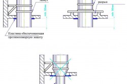
Lining chimneys performs two functions: protecting the barrel from the thermal and aggressive effects of flue gases and condensate. To exclude the possibility of condensate formed on the surface of the overlying lining link getting into the gap between the barrel and the underlying link, it is covered with a canopy made of acid-resistant products called “tear-resistant.”
Quite often, the lining is applied using shotcrete, ensuring gas tightness.
In the base part of the pipes, with significant openings for supply gas ducts, the lining thickness is taken to be 1.5 bricks or 380 mm. Considering that currently several types of linings made of piece ceramic products are used in chimneys built in different periods, it is advisable to illustrate their designs.
Until about 1960 chimneys were operated at a flue gas velocity at the exit not exceeding 14-16 m/s, and at a vacuum along the entire height of the smoke channel. The temperature of the flue gases was in the range of 180-250 C, which excluded the conditions for the formation of condensation. The lining design met these conditions.
In the early 60s, there was a significant decrease in the temperature of flue gases to 70-180 C and the use of high-sulfur fuel, which resulted in the formation of sulfuric acid condensate in the pipes. In this regard, the need arose to protect the load-bearing reinforced concrete pipe shaft from sulfuric acid corrosion and a lining design appeared using acid-resistant products and a layer of vapor and moisture insulation, usually made from bitumen mastic, although sometimes other coatings from sheet materials or coal tar epoxy resins. It should be noted that bitumen mastic required the installation of a pressure layer in the lining.
In the presence of high gas velocities (25-40 m/s), excess static pressure arises in the smoke channel of the pipe. In this regard, a backwater of aggressive flue gases is created, which penetrate through the lining of piece ceramic products to the inner surface of the reinforced concrete shaft, which has more low temperature compared to flue gas temperature. As a result, they are cooled below the dew point and sulfuric acid condensate falls on the inner surface of the pipe shaft, which leads to accelerated corrosion of the load-bearing structures.
A problem arises - either strengthen the anti-corrosion protection of the barrel, or look for new design linings.
Taking into account the acute shortage of reliable anti-corrosion coatings and their high cost, work began to improve the lining. Thus, a backpressure design in a forced-ventilated gap was developed. In chimneys with a lining of this design, an additional volume of air is supplied to the gap between the barrel and the lining by a fan and a pressure is created in the gap that exceeds the pressure of the flue gases, as a result of which the filtration of gases to the supporting pipe shaft must be prevented. To increase the crack resistance of the lining, air. Supplied into the gap, it must be heated to reduce the temperature difference on the working and outer surfaces to a minimum.
There is also a lining design with a naturally ventilated gap. The difference in design lies in the gradual reduction in the width of the gap along the height of the pipe, which should ensure that a certain back pressure is maintained in it.
In all of the above options, a lining made of pieced ceramic products requires large amounts of physical labor, time, machinery, and equipment for its construction, as well as careful implementation of measures for the safe performance of work. In addition, each of the options has its own vulnerabilities associated with the disadvantages inherent in all brick structures.
Therefore, the appearance of a monolithic lining in the early 80s, the design of which can significantly reduce labor costs, the duration of work and their cost, is quite justified.
Reinforced concrete pipes with monolithic lining began to be built in 1970. By that time, due to environmental conditions and the lack of effective ways Purification of flue gases from sulfur and nitrogen oxides at many facilities required the construction of gas exhaust pipes with a height of 250, 320, 370 and 420 m.
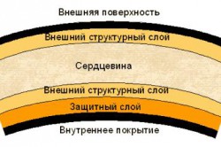
The search for more industrial methods of pipe lining led to the development of two-layer monolithic pipes. The outer shell was made of heavy concrete, the inner monolithic layer of lightweight polymer concrete.
In this case, a higher level of reinforcement of the outer shell was provided to increase the crack resistance of the shaft, since when the inner layer of lightweight concrete is heated, the temperature stresses must be absorbed by the reinforced concrete shaft.
A monolithic lining made of lightweight polymer-cement concrete serves to protect the load-bearing reinforced concrete shaft of chimneys. Designed for the removal of slightly aggressive gases produced by burning low-sulfur coals. To prevent excess pressure from appearing in pipes with this lining, their upper part has a cylindrical shape.
Accelerated technology for constructing pipes is ensured by the fact that concreting the shaft and lining is carried out using one set of formwork, and the separation of layers of different concretes is achieved by installing a separating diaphragm made of metal wire mesh with 4x4 mm cells.
Thirty years of experience in operating two-layer reinforced concrete chimneys has shown their high reliability. Over twenty years of operation, for example, Volzhskaya CHPP - 2, which operated for a significant part on fuel oil, the polymer-cement lining of a chimney 270 m high had a decrease in strength on the side in contact with flue gases to a depth of 2-5 mm.
The lining of prefabricated chimneys to protect the shaft from condensation is usually carried out by gunning with a layer thickness of 25-30 mm with a composition of quartz or fireclay sand and Portland cement.
To protect the barrel from high temperatures, a lining is made from KVI-650 products. Modern products made from ceramovermiculite KVI-650 (TU 21-RF-129-88), intended for lining thermal units with operating temperature up to 1100 o C. The use of KVI-650 in furnace lining allows saving significant energy and material resources. This material is easy to process (sawed, drilled, etc.), is not afraid of water, is durable, and is resistant to rapid temperature changes.
It should be noted that today there is no data on the long-term service of linings of old chimney reinforced concrete pipes.
The main disadvantages when using linings of any design are the impossibility of eliminating damage that occurs for various reasons without stopping the pipe for a long period of time, the technological complexity of carrying out repair work, as well as great difficulties in monitoring its condition during operation.
Lining materials
chimney lining gunite
In the case of removal of low-aggressive flue gases through a pipe, clay bricks are used for lining - patterned and ordinary plastic pressing. In this case, cement-clay mortars are used for laying the lining. When flue gases are highly aggressive, acid-resistant normal and radial bricks are used for lining. In terms of physical, chemical and mechanical parameters, this brick must meet the requirements given in table. 1.
Table 1 Physico-chemical and mechanical properties of acid-resistant bricks.
Brick laying is carried out on andesite putty, in which the binder is sodium-based liquid glass.
The composition of the acid-resistant solution includes, in addition to liquid glass and hardening initiators (sodium silicofluoride), finely ground filler and acid-resistant filler (sand). The binder in the acid-resistant solution is a silicic acid gel, released as a result of the interaction of liquid glass with a hardening indicator.
When burning high-sulfur fuel, it is recommended to use an acid-resistant solution of composition III and the use of an acid-resistant solution of composition I is allowed. In conditions of alternate combustion of high-sulfur and gas fuels or combustion of low-sulfur fuel with high humidity of exhaust gases, the use of acid-resistant composition II is recommended.
To prevent the penetration of gases and protect the inner surface of the reinforced concrete pipe shaft, it is necessary to completely fill the joints of the lining masonry with jointing them or grout the inner surface and oxidize with a 20% sulfuric acid solution 3-4 times. To seal the gaps at the junction of the lining links, asbestos cord is used. Acid-resistant tiles are used to protect ceilings and floors in the lower parts of chimneys exposed to acids. In the latest new designs of flue pipes as building materials applied artificial materials flint concrete and polymer concrete, and to protect gas ducts - silicate-polymer concrete.
Silica concrete is obtained by autoclave processing of a mixture of high-silica silicate block, finely ground quartz sand, acid-resistant fine and coarse aggregate. The difference between siliceous concrete and conventional concrete is the use of a new binding material called siliceous cement. Siliceous cement consists of ground quartz glass, which contains SiO 2 in amorphous form, an alkaline solvent and finely ground particles of crystalline quartz. Quartz glass is obtained by melting quartz sand in special furnaces such as glass furnaces. The filler for flint concrete is, as in conventional concrete, quartz sand and gravel.
The study of the phase composition and structure showed that silica concrete is characterized by a complex conglomerate porous structure. The pores are mostly closed in nature with a size ranging from 0.01 to 1.5 mm. The total porosity is 11 - 13%. The structural features of silica concrete and the phase composition of the cementing substance predetermine its physical, physical-mechanical, construction, and thermal properties. physical properties and durability.
In table Table 2 shows the properties of silicon concrete on Ovruch quartzite with a silicate block consumption of 320 kg/m 3.
Table 2 Basic properties of silica concrete
Slabs are formed from flint concrete, which are then subjected to thermal and wet treatment in autoclaves at a pressure of 0.13 MPa and a temperature of 190 C for about a day. These plates are used for the installation of gas exhaust shafts.
Silicate-polymer and cement-polymer concrete are used in the construction of pipes according to the “pipe-in-pipe” design principle, such as a pressure lining, and in the construction of gas ducts in the form of a concrete mixture.
Bibliography
1. Duzhikh F.P., Oslovskikh V.P., Ladygichev M.G. Industrial chimneys and ventilation pipes: Reference publication / Edited by F.P. Duzhikh. - M.: Teplotekhnik, 2004 - 464 p.
2. Chimneys / a.m. Elshin, M.N. Izhorin, V.S. Zholudov, E.G. Ovcharenko; Edited by S.V. Satyanova. - M.: Stroyizdat, 2001. - 296 p.; ill.
Posted on Allbest.ru
...Similar documents
Application of gases in technology: as fuel; coolants; working fluid to perform mechanical work; environment for gas discharge. Regenerators and recuperators for heating air and gas. Use of flue gas heat in waste heat boilers.
test, added 03/26/2015
Description of the preparation process solid fuel for chamber combustion. Creation of a technological scheme for energy and heat production. Carrying out calculations of the material and heat balance of the boiler unit. Methods for cleaning flue gases from sulfur and nitrogen oxides.
course work, added 04/16/2014
Perform fuel combustion calculations to determine the amount of air required for combustion. Percentage composition of combustion products. Determining the dimensions of the furnace working space. Selection of refractory lining and method of flue gas disposal.
course work, added 05/03/2009
Recuperator design. Calculation of resistance along the path of air movement, total losses. Fan selection. Calculation of pressure losses along the path of flue gases. Hog design. Determination of the amount of flue gases. Calculation of the chimney.
course work, added 07/17/2010
Calculation of lining dimensions, masonry thickness, temperature at the junction of layers, thermal conductivity for the working and heat-insulating layers. Plotting graphs of temperature dependence of joints. Design blast furnaces. Finding the average temperature of the lining.
course work, added 10/07/2015
Determination of heat loads and fuel consumption of a production heating boiler house; calculation of the thermal circuit. Rules for the selection of boilers, heat exchangers, tanks, pipelines, pumps and chimneys. Economic indicators installation efficiency.
course work, added 01/30/2014
Calculation of the dimensions of the lining, the thickness of the masonry walls and the dome of a water heater with a volume of 3300 m. Determination of the temperature at the junction of layers and thermal conductivity for each layer. Plotting a graph of the temperature dependence of the joints and the lining diagram of the air heater.
test, added 10/07/2015
Features of the thermal calculation method for DKVR type boilers that do not contain a superheater. Identification of the volume and composition of flue gases. Determination of fuel consumption, adiabatic combustion temperature. Calculation of a cast iron economizer VTI, a bundle of boiling pipes.
training manual, added 03/06/2010
The concept of permanent connections water pipes. Features of butt or socket welding of pipes. Specifics of bonding by gluing, materials used and process sequence. Advantages of this connection method compared to welding.
presentation, added 04/21/2014
Operating principle, design and speed modes of ball mills. Hadfield steel and its physical properties. Development of a method for strengthening the lining of a ball mill under operating conditions. Calculation of the time of the proposed strengthening treatment and work.
In order to ensure the smooth functioning of systems, it is necessary to carry outpipeline lining and coating of pipes with anti-corrosion materials. This will make it possible to repair and restore industrial equipment in as soon as possible and will avoid wear and tear in the future.
Every year, leaks, regardless of their cause, result in unimaginably high repair costs. One of the problems is also the danger to person and environmentchemical leaks. To limit damage, quick and safe means are always needed. Restoration and repair technologies must be available around the clock and should be as safe as possible.
Transporting liquids through pipelines requires highly efficient wear protection And corrosion. The ingress of particles and foreign substances, regardless of their size, threatens equipment with chips, cracks and premature wear. In this case, leaks and local damage occur quickly and unhindered.
Pipeline lining, anti-corrosion pipe coating
Anti-corrosion coating of pipes, anti-corrosion coating of pipelines, internal anti-corrosion coating of pipes
It includes not only external treatment with polymer materials, but will also allow internal anti-corrosion coating of pipes.
![]()
For pipeline lining And anti-corrosion pipe coatingour company suggests using elastomerMetaline 700 series. Given elastomeric coatingforms a dense barrier to moisture penetration and thereby reliably protects the surface from corrosion. Elastomers Metaline 700 series can be used to restore anti-corrosion coatings and are easily subject to local repairs.
- Lining is a protective internal or external lining of heat exchange equipment, chemical apparatus, pipelines, pickling baths, containers, reservoirs, columns, reactors, etc. protecting against thermal and chemical influences of aggressive environments. Lining helps extend the life of existing equipment and save money on replacing equipment that has become unusable. Lining products with fluoroplastic has become widely used. Possessing high chemical resistance and the ability to use coatings for high temperatures, fluoroplastic lining is widely used in various industries.
Pipe lining is used to protect against the effects of aggressive environments during their transportation through pipelines. Lining of pipes is necessary even when they interact with water, which has a depassivating effect in relation to metal surface. Thanks to pipe lining, the service life of pipelines and equipment is significantly increased. For pipe lining, fluoroplastic is used, which has a number of important characteristics necessary to protect the lined surface.
The Plastpolymer-PROM company carries out lining of pipes and pipelines with fluoroplastic according to customer dimensions. Protective coatings for pipeline flow parts, created by lining with fluoroplastic, provide high performance qualities and properties:
- wide range of mechanical properties;
- good dielectric properties;
- high electrical strength;
- low friction coefficient;
- low wear values;
- resistance to various aggressive environments at room and elevated temperatures;
- atmospheric, corrosion and radiation resistance;
- weak gas permeability;
- non-flammable or self-extinguishing when ignited.
Plastpolymer-PROM LLC offers services for lining pipes and pipeline connections with fluoroplastic:
- steel pipes lined with fluoroplastic-4D are used for pipelines transporting any aggressive media (with the exception of molten alkali metals, chlorine trifluoride and fluorine) at a media pressure of up to 1.6 MPa;
- tees, bends, crosses, reducers, steel flanges, lined are used to connect lined pipes into main pipelines transporting aggressive media;
- steel bellows, lined, are used to connect pipelines transporting aggressive media for compensation linear dimensions pipelines at various thermal loads (from –60 to +250°C) and to reduce vibration loads.
The metal shell of pipes, tees, bends, etc. for lining is manufactured by the consumer according to drawings agreed upon with Plastpolymer-PROM LLC.
The operating temperature of lined pipes and pipelines is from -60°C to +230°C.
Add to bookmarks
Chimney lining: main points
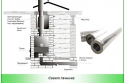
Futerovka means “lining” in German. The chimney lining includes a special finish to provide protection various surfaces from all kinds of damage and represents a frontier of work on laying and strengthening various structures, depending on what these structures are intended for. This can be lining the inside of fireboxes, pipes, furnaces or containers using bricks or special blocks. The lining can be chemically resistant, fire-resistant or for thermal insulation purposes. Based on their chemical composition, the lining is divided into basic and acidic.
Industries of lining work
In the mining industry, lining work is carried out to protect various equipment for the transportation and handling of various cargoes. The lining protects against impacts that cause damage and enhances the fire-resistant properties.
Lining is mainly used in the metallurgical industry, since the main equipment is blast furnaces. Not only the furnaces themselves are lined, but also the pipes, furnaces and ladles.
Lining work is mandatory for these areas of production, since their implementation improves the fire-resistant qualities of the equipment.
As well as strength under mechanical stress various types. After lining, the furnaces are significantly strengthened and can be easily moved increased loads such as friction, sticking and elevated temperatures. Service life increases.
Specifics of lining work
The choice of material for lining depends on what object you need to strengthen. The production of lining work involves applying a special product to the internal surface of the object. This product is made on a vermiculite basis. This substance has many positive qualities that increase service life. When used, the fire resistance and heat resistance of the object increases. The material has increased insulating properties and is less susceptible to chemicals. And another plus is minimal electrical conductivity.

The lining of blast furnaces is carried out using refractory materials such as fireclay bricks. Various blocks of carbon composition, bricks with a high clay content or with silicon carbide components can also be used.
Materials for lining chimneys
If the chimney trunk is made of brick, then the following brands of brick are used for lining:
- by strength (not lower than 100);
- by frost resistance (from 25-50).
When laying the lining of a chimney, which removes gases (with temperatures up to +500°C), ordinary clay bricks are used using mortar, a clay-cement mixture. If the temperature is higher, then fire-resistant fireclay products of the ShB, ShA brands and cement-chamotte mortars are used.
Lining a chimney made of acid-resistant bricks involves the use of acid-resistant putty based on liquid glass.
Linings made of ground fireclay and sand in a 1:3 weight ratio or aluminous cement are considered quite effective. The use of aluminous cement significantly increases the resistance of linings to acid, and at elevated temperatures the resistance to mechanical damage increases. Thus, the heat resistance of sand-based concrete is no higher than 250 degrees, and that of chamotte-based concrete is up to 1000 degrees.
Features of lining work
The process of laying out refractory materials in stages is the lining process. The base of the blast furnace (flat) is lined with blocks of brick, which contains a large amount of alumina material. The resulting space must be covered with specially prepared putty. It is made from a mortal material and must match the type of brick used. The above material is obtained by mixing fireclay and clay. The fireclay is first crushed to a powdery state.
For critical masonry, soda and stillage of sulfite-alcohol composition are added to the material used. It increases the adhesiveness of the material, which enhances the adhesion of the brickwork. If the masonry is made of carbon blocks, the space between the seams must be filled with a substance of a different quality. This is a paste-like mass made from coke.
Simply put, lining a chimney involves laying materials with fire-resistant qualities, and then sealing the resulting seams. Lining work is not considered very difficult. But this is a labor-intensive process. The main thing is to use the materials for their intended purpose, observing technological process and safety precautions.
This is the process of applying a multi-layer protective layer of fiberglass laminate to a metal or concrete surface. The finished coating forms a solid layer tightly adhered to the surface. There are no joints or cracks on it.
The service life of such a lining, subject to operating rules, is more than one decade.
With the help of such a lining, corrosion protection is provided, and at the same time the tightness and density of the processed equipment is restored.
Chimney lining: repair
Repairing chimney linings is quite labor-intensive and difficult task. But it can be solved by carrying out modern technological work using repair mixtures specially designed for this.
When natural gas is burned, smoke is produced containing up to 18% moisture in one unit of volume. This moisture, concentrated in the flue gases, is a mode of incomplete loading during the operation of chimneys; repeated stops and starts form condensation on the surface of the lining inside the pipe. As a result of these factors, the lining of chimneys suffers significantly. Basically these are damages such as:
- washing out of the mortar between the masonry and, as a result, the collapse of the brickwork;
- destruction of the brick lining and chimney trunk as a result of alternate thawing and freezing;
- violation of thermal insulation between the lining and the barrel, as excess moisture gets there;
- filtration of moisture through the seams onto the outer surface of the chimney trunk.
Most of the damage listed above can be eliminated only after correcting the gas tightness of the lining and the impossibility of gases entering the elements of the facility.
The quality of lining repair work directly depends on both the materials used and the approach to this problem. A comprehensive solution is required, which includes:
- initial determination of the reasons contributing to the destruction;
- taking into account all existing conditions when making a decision on repairs (available equipment, qualifications of employees; time frames allotted for repairs, etc.);
- compliance of the work performed with the technological design.
Destruction of chimney linings and measures for their restoration
The main material from which the lining of chimneys is made is quite rarely susceptible to destruction. In most cases, damage to the seams and anti-corrosion coating of the lining is noted. Damage in the form of swelling of brick joints under the influence of flue gases that contain sulfur compounds is less common.
The main reason for the destruction of chimney linings and the appearance of cracks is the discrepancy between the operating temperature parameters and the design ones. With such a violation, thermal stresses arise in various parts pipes

To increase the reliability of chimney linings, you must first do the following:
- Restoring the walls of gas ducts made of brick or reinforced concrete involves lining the inside with acid-resistant or gunite-silicate polymer bricks, eliminating the use hollow core slabs when replacing gas duct covers.
- If the chimney lining is completely or partially destroyed, there is a need to restore it using acid-resistant bricks (as an alternative brickwork You can use a metal or fiberglass barrel installation). The pipe head should be made of acid-resistant solution or cast iron links.
- Use reinforced concrete clips in order to restore the load-bearing capacity of reinforced concrete trunks;
- Avoid leakage of outside air into chimneys.
- Practice the method of inspecting the condition of pipes using a thermal imaging method, which does not require stopping the operation of the pipe, and efficiently and quickly identifying the location of damage.
As for the fiberglass chimney lining, in this case the load-bearing brick or reinforced concrete shaft is very well protected from condensate and flue gases. It is not in danger of metal corrosion. The advantages of fiberglass include its weight (about 15 times lighter than a brick lining), corrosion resistance, and a longer service life. There is an option for gas exhaust barrels, produced at the factory, in the form of segments that are subject to subsequent assembly.
Inspection, supervision and repair of industrial chimneys
Any inspection includes experts. An agreement is concluded with the customer and, in accordance with the agreement, a periodic inspection is carried out, during which a camera with a telephoto lens, binoculars, a video camera, a theodolite, a thermograph, and an electronic microcalculator are used.
The inspection is carried out using climbers’ equipment on external stairs and special platforms of the structure being inspected. The inspector has a voice recorder and a camera at his disposal. The inspection reveals the presence of corrosion of metal and reinforcement, as well as the detection of cracks. If necessary, material samples are drilled. When a possible shutdown occurs, the internal surface of the pipe is inspected and remotely controlled instrumentation is used to record videographic data.
Installation also takes place various devices, controlling the resonant vibration frequency of the structure. As a result of the data obtained, invisible cracks are identified, signals are received about reduced quality of the material and reduced stability of the structure.
Depending on the operating mode of the chimney, inspection is carried out once every 3 years or once every 6 years.
At the end of the inspection, a report is prepared indicating the existing defects and damages, the reasons for their occurrence, the expected subsequent development of the violations and the expected remaining service life. Recommendations are offered for the operation of the chimney to maintain it in good condition.
On the customer's side, a registration book is maintained, which contains sections such as the characteristics of the chimney with drawings, the conclusion made by the inspectors, recommendations and a report on the repair work carried out.
Documentation |
Purpose
Steel pipe lined with a modified thermo-expandable polymer sleeve of the TFR series- This is a multi-layer two or three-layer pipe structure consisting of steel and internal polymer pipes. The steel pipe carries the load, and the polymer pipe protects the steel pipe from internal corrosion. The steel pipe is protected from external corrosion by a polymer or anti-corrosion paint coating.
Lined pipes are manufactured on the basis of technical specifications TU 1394-015-75454983-2014.
Steel pipes lined with a modified polymer sleeve are used for the construction of oil field and process pipelines transporting water-cut oil, wastewater containing hydrogen sulfide, as well as other liquid and gaseous media to which the composite polymer material is chemically resistant - a thermally expandable, complexly modified composite polymer based on polyolefins.
- The modified composite polymer material used as a lining layer has significantly higher parameters in comparison with LDPE and HDPE polyethylene:
- by operating temperature (-60 °C – +135 °C),
- chemical resistance, low gas permeability (up to 10 times),
- increased wear resistance (up to 30 times),
- mechanical strength (up to 3 times).
These parameters significantly increase the service life of TFR compared to steel pipes and provide the main competitive advantages of lined pipes of the TFR series in relation to metal-plastic (MPT), polymer-reinforced (PAT and TTA) and polyethylene (polypropylene) lined steel pipes.
Due to the low roughness of the inner surface of lined TFMR pipes, which does not decrease over time, throughput they are 10-15% higher than that of metal pipe, other things being equal, which allows the use of smaller-diameter TFMRs.
Nomenclature of lined pipes of the TFMR series
Conditional pass: 50; 70; 80; 100; 125; 150; 200; 250; 300; 400; 500 mm.
Pipes with a diameter from 57 to 530 mm, having manufacturer certificates, are used as a steel shell:
Steel water and gas pipelines that meet the technical requirements of GOST 3262;
Seamless hot-deformed steel, meeting the technical requirements of GOST 8731. rough assortment according to GOST 8732;
Seamless cold-deformed steel that meets the technical requirements of GOST 8733. Pipe range in accordance with GOST 8734;
Straight-seam electric-welded steel, meeting the technical requirements of GOST 10705, pipe assortment GOST 10704.
It is allowed to use pipes of the same range that meet the requirements of other technical specifications, or pipe standards with external insulation, agreed with the Customer.
Wall thickness:
- steel 3 – 20 mm,
- lined 2.0 – 5.0 mm.
Maximum deviations: by thickness steel pipe: in accordance with GOST 8732-78, lining polymer layer ± 15%.
As a lining layer, a polymer thermo-expandable complex modified hose of the TPP series is used according to TU 2248-001-75454983-2013, made from a polyolefin composite with subsequent gamma quantum modification.
Measured pipe length: from 6 to 12 m. By agreement with the customer, it is possible to manufacture pipes with various lengths and configurations up to 12.0 m.
Connection type: flanged, coupling, welded for operating pressure up to 25 MPa (according to OZEU LLC technology).
The maximum operating pressure of lined pipes Pwork.max (MPa) is regulated by the parameters of the steel pipe.
Temperature of the transported medium: from – 60 to + 135 °C.
Transported medium:
- water: technical, drinking, distilled, mineralized, sea;
- oil and oilfield wastewater;
- pickling solutions, galvanic departments and chemical cleaning enterprises;
- liquid and gaseous ammonia;
- acids: 30% sulfuric, 25% nitric, hydrochloric, hydrofluorosilicic, hydrofluoric;
- gas and gas-liquid mixtures, including natural gas and associated petroleum gas.
The continuity and thickness of the lining layer is guaranteed by production technology and checked by non-destructive testing devices. If necessary, pipes are tested for impact strength at temperatures down to -60 °C.
The pipes withstand test hydraulic pressure in accordance with GOST 3845-75.
Pipes must withstand the flattening test in accordance with GOST 8695-75.